The HMMWV uses a common cooler frame containing cores for both transmission fluid and engine oil. 2930-01-168-7911 [2930011687911
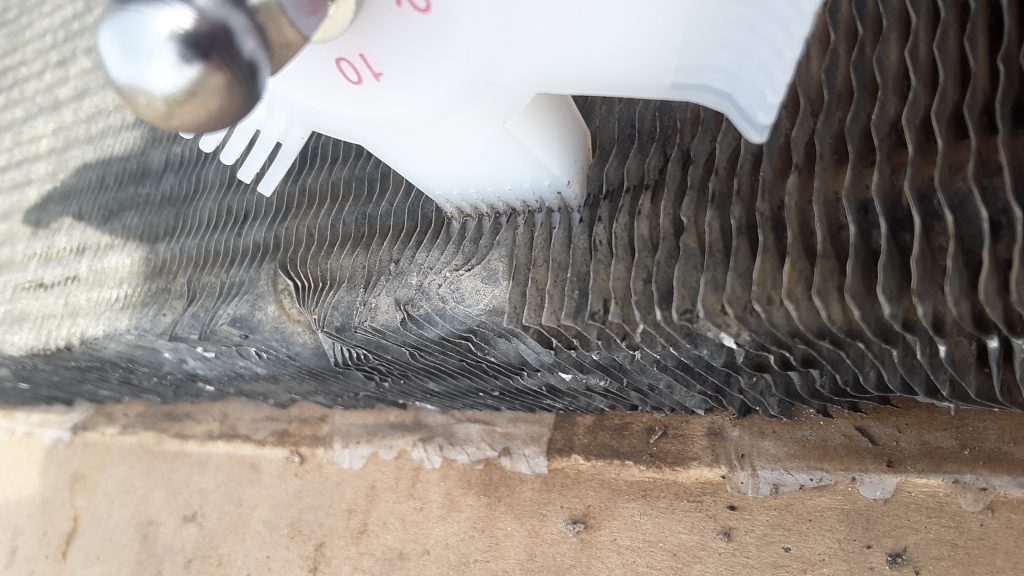
Cooler fins being straightened with a Robinair 18403 Fin Comb (also known as a “fin straightener) Note the use of the 10 fins/inch com
Quite often, the cooling fins are damaged (by being bent or collapsed) at the top and bottom of the unit, and often within the main area of the cores themselves.
Our unit had crushed and bent fins on the top, bottom, front and back. The picture above shows use of a fin comb to straighten out the fins. Although we used a Robinair with multiple combs, you could simply acquire a 10 fins/inch comb to accomplish the same task.
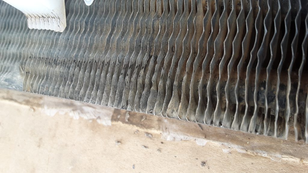
Although a tedious and time consuming task, this will ensure not only optimum airflow and cooling, but it also eliminates the somewhat unsightly bent fin situation.
Cooler shows straightened fins after passes with fin comb.
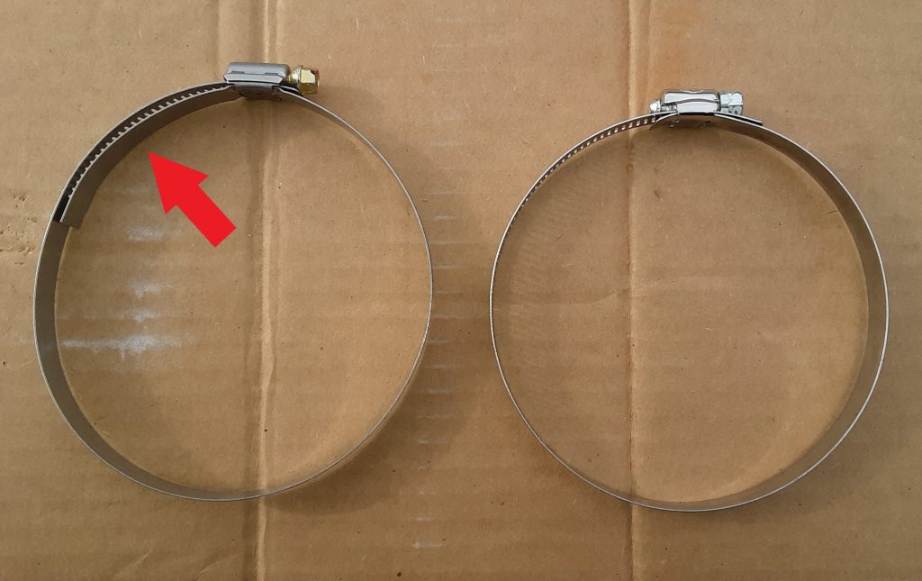
There are two primary types of “open” hose clamps. The two pictured above are SAE Size 72, which we determined is the commercial equivalent of clamp 4730-00-359-9487 [4730003599487].
On the right is the standard hose clamp. On the left is what is referred to as a “liner” hose clamp. The Red Arrow points to a shield that protects the hose from extruding through the “rack” portion of the hose clamp. Liner clamps are often called “military clamps,” but in fact, the liner is designed for clamping softer materials such as silicone hoses.
This size clamp is called out to tighten the 90 degree hose used to connect to the fording stack extension 2510-01-198-0333 [2510011980333] and to the air cleaner. (See Figure 398, Item 31).
Of interest, the standard hose clamp in Size 72 worked perfectly for the fording tube application, however the “liner” clamp was too small. In fact, the liner clamp was manufactured by Breeze, a company that is a supplier of hose clamps to the military.
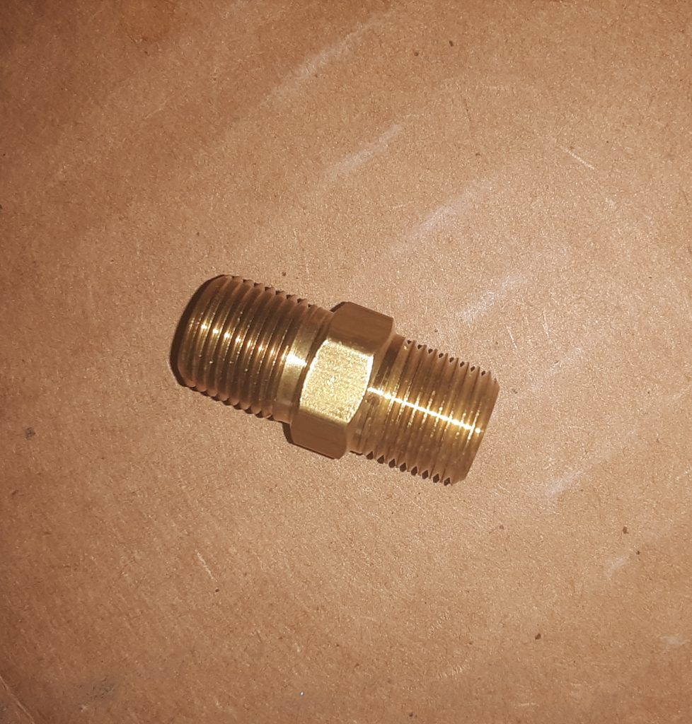
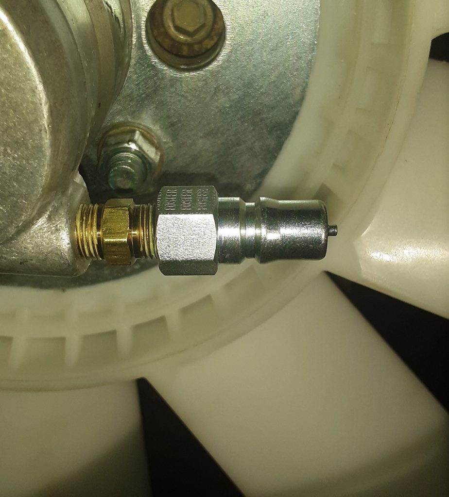
In an earlier post, we discussed interchange for the quick connector used on the fan clutch. Pictured below is the commercial equivalent of 4730-00-900-3296 [4730009003296] (Figure 178, Item 23), which is simply a 1/8″ x 1/8″ NPT nipple.
Although there are varying opinions on pipe dopes v. teflon tape, we prefer to use Rectorseal #5. It does come second only to anti-sieze at managing to make a mess, but we have successfully used this material for decades without encountering leaks.
Pictured below is the nipple and the quick disconnect discussed in the earlier posting. This is essentially one half of what is shown as Item 7 in Figure 178, and has been assembled to the fan clutch.
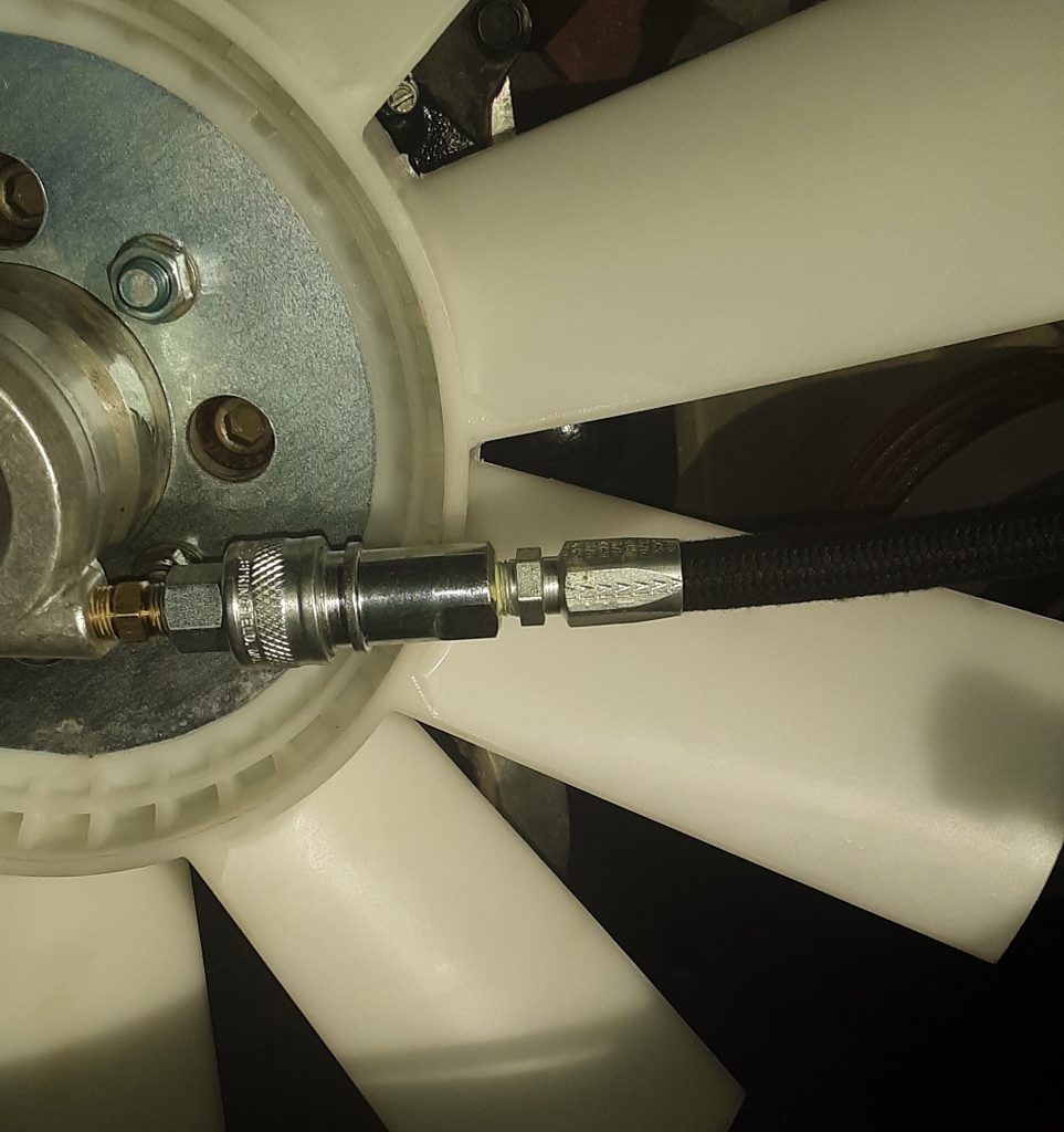
Below is the quick disconnect connected together along with hose 4720-01-189-0853 [4720011890853]. Note we have applied Rectorseal to all pipe threads.
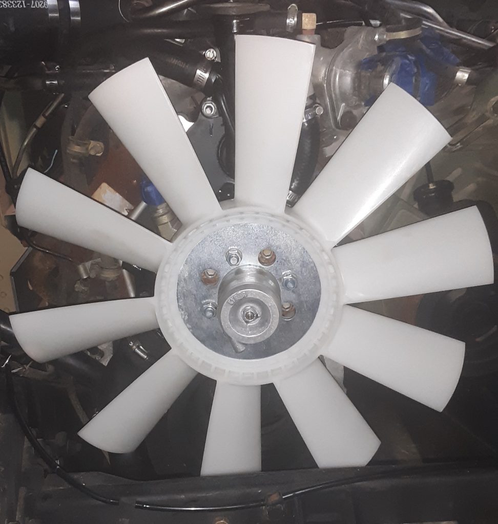
The fan used for either 6.2 or the 6.5 NA on the v-belt application is4140-01-211-8403 [4140012118403]. As discussed in this post, the quality and materials appear to be comparable to OEM. The fan itself centers on the diameter of the fan clutch. We had to dress the inside of the fan in order to install it. We do not feel this to be a flaw, but rather precise hand-fitting of the fan to the fan clutch.
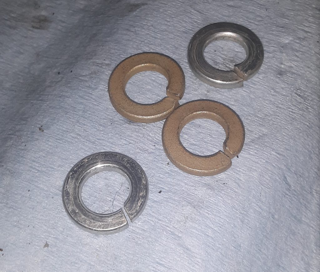
The lock washers taken off of the fan appeared to have not retained its spring-like characteristics. We believe they used Grade 5 or less washers on installation. We replaced those washers with Grade 8 (the gold ones) to ensure locking capacity. (Of note, we also used Blue Loctite as an extra safety measure).
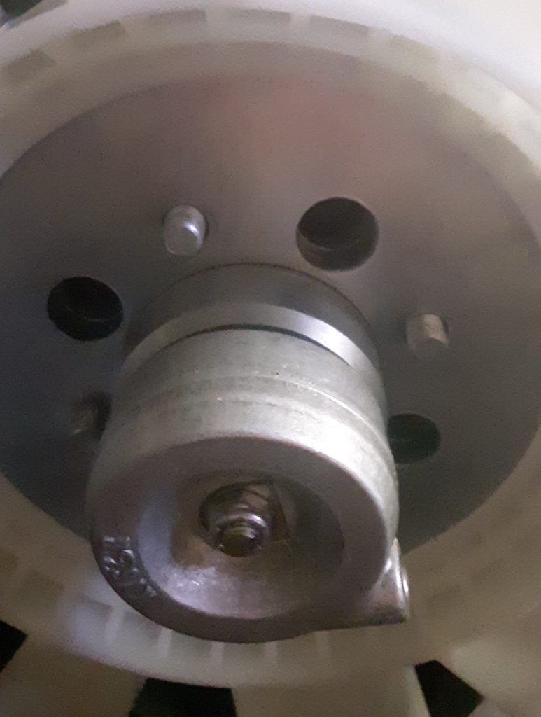
The silver lock washers were removed from the vehicle, the gold Grade 8 ones were used to replace them. Note: there are four lock washers required, only two of each were photographed as examples.Picture of fan assembled to fan clutch.
Having disassembled, inspected and repaired the fan clutch in a prior post, we install the clutch to the water pump (of which we discussed interchanges).
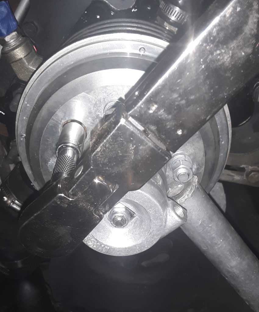
Torquing fan clutch to water pump bolts. Note use of aluminum tubing to stop rotation of fan assembly during torquing.
We were unable to easily locate the torque specifications for the fasteners. We referred to Alma Bolt Company & Prime Fasteners’ torque specifications for Grade 5 and Grade 8 bolts. Being that the fasteners on our powerplant were socket head (allen bolt), this is generally an indication of a Grade 8 fastener. According to Alma Bolt’s chart, a 3/8″ Grade 8 has a specified torque of 44 ft. lbs. for a plain bolt, and 33 ft. lbs. for a plated (or wet) bolt.
We set our torque wrench to 32 ft. lbs. and after applying Red Loctite to each fastener, evenly tightened down the fan clutch. After subsequent review, we note that TM 9-2320-280-20-2 specifies 45 lb-ft (page 3-135 Change 3 at c.1.). This is within the specifications provided in the Alma Bolt chart, as the TM does not specify use of loctite which lubricates the thread causing a lower torque reading to equal the same “tightness” as a higher torque with dry threads.
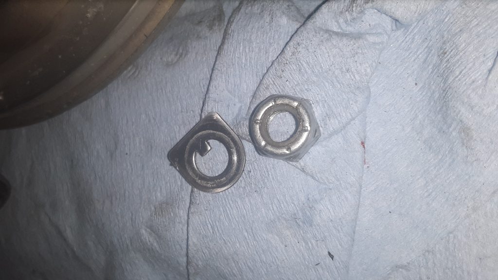
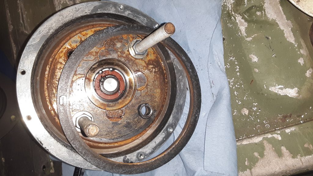
The first step (once the fan clutch has been removed from the engine) is to remove the lock nut 5310-01-194-0481 [5310011940481] and locking tab 5310-01-189-8468 [5310011898468] from the face of the cylinder assembly 2930-01-189-1744 [2930011891744].
Self locking nut and locking tab from front of fan clutch
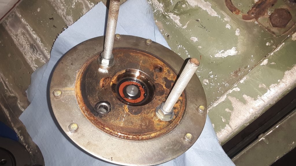
Next, install two 3/8 x 5″ (or so) bolts as shown below and tighten the shaft assembly 4079-38441-01 (no NSN) into housing assembly 4040-38442-01 (no NSN) enough to release the spring tension to remove the six capscrews 5305-00-052-6456 [5305000526456] holding the back plate on . Remove the backing plate. Do not, under any circumstance, remove the backing plate screws without a method (such as the bolts indicated in the picture) in place. There is a spring under pressure and failure to properly restrain it can lead to serious injury or even death.
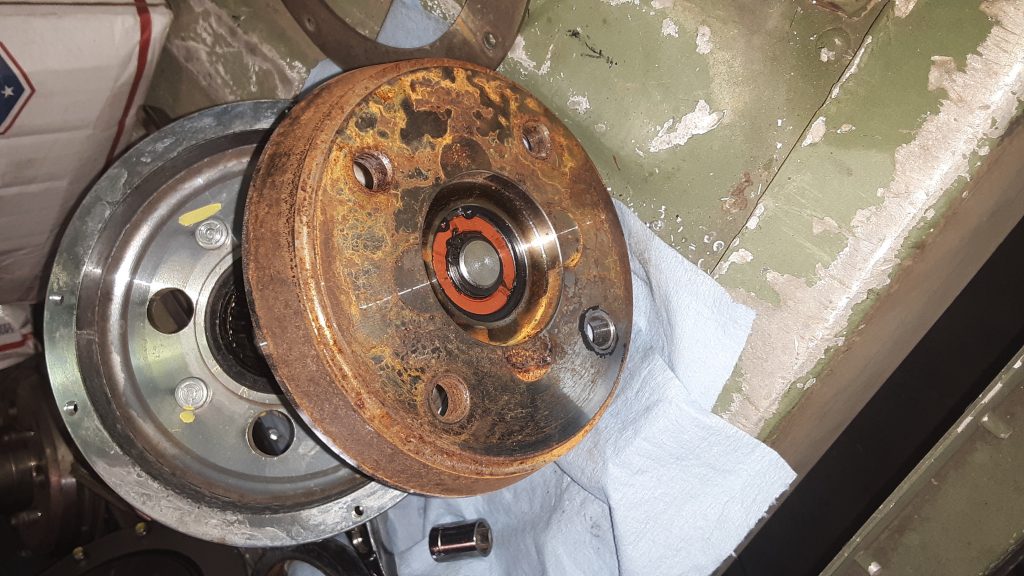
Once the backing plate is removed, the clutch lining 2930-01-189-8643 [2930011898643] can be removed. It is not uncommon to stop at this phase, if the problem was that the fan wouldn’t DIS-engage because the lining had “frozen” to the shaft assembly. If not being replaced, the lining can be cleaned up using emery cloth or similar. The clutch surface of the shaft assembly can also be polished in this manner.
Friction lining removed, shaft assembly under spring tension (held safely by 3/8 bolts).
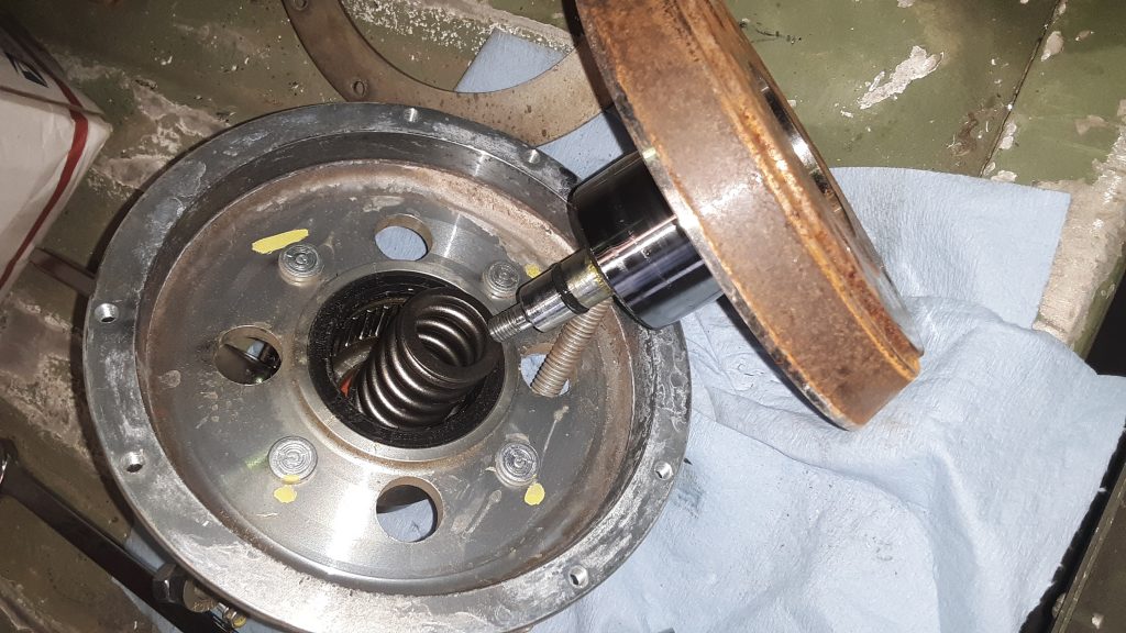
Once the spring pressure is completely relieved by slowly releasing tension on the safety bolts, the safety bolts can be removed. Inspect the inner bearings as well as the Torrington-style bearing and seals. Replace any damaged parts.
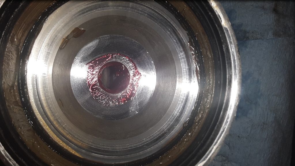
The below view shows the spring, seal and inner bearing. Ensure all O-rings are serviceable, and that the bearing surface on the shaft assembly is not damaged.
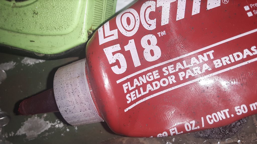
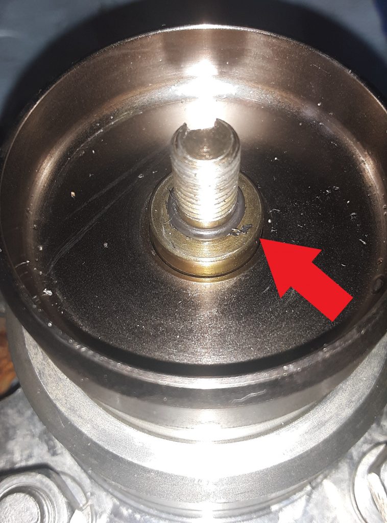
On reassembly, there is often leakage at the front O-ring, even when a new O-ring is used. Because of the likelihood of leakage, we recommend use of Loctite® 518 (or similar) on the sealing surface indicated by the Red Arrow in the picture below, as well as the corresponding location.
Reassemble the entire unit as it was disassembled. Again, Use safety precautions during reassembly because you are putting a lot of potential energy into the spring as it is tightened. Improper assembly can potentially cause serious injury or even death. If you have any doubts, please refer this to a professional or person experienced in assembling spring loaded machinery.
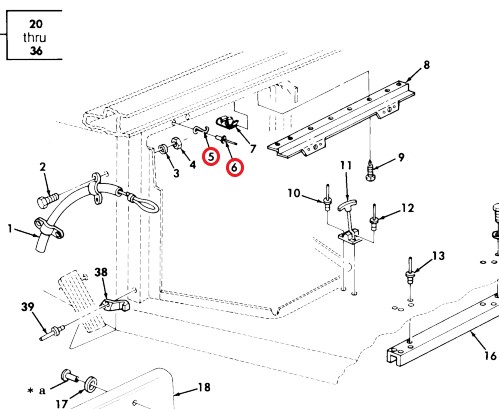
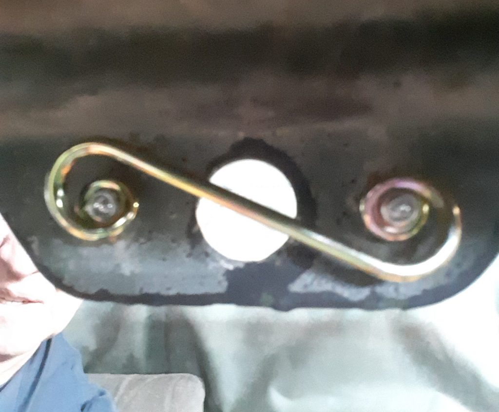
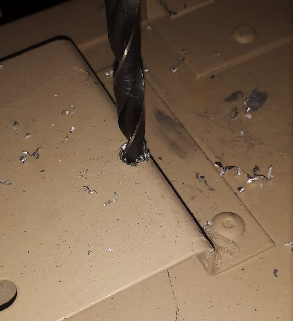
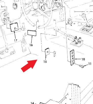
To replace the quarter turn fastener springs 5325-00-449-3001 [5325004493001] (Item 5 above), drill out the existing rivets 5320-00-083-5009 [5320000835009] (Item 6) with a 1/8″ drill bit.
These parts can be substituted as follows: First, the quarter turn spring can be substituted with Dzus or generic quarter turn fastener springs with the dimensions of spring height to latching surface .150″ to .175″ and measurements of 1-3/8″ eye to eye. Second, the rivets are simply 1/8″ diameter x 5/16″ length.
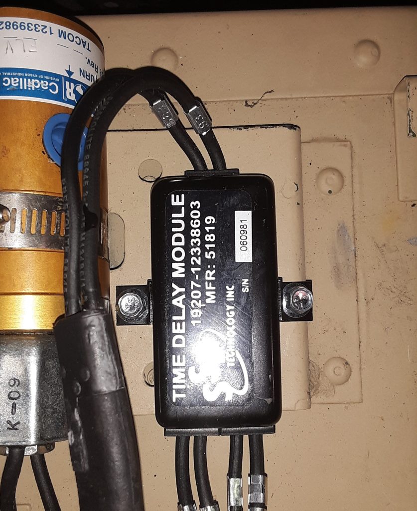
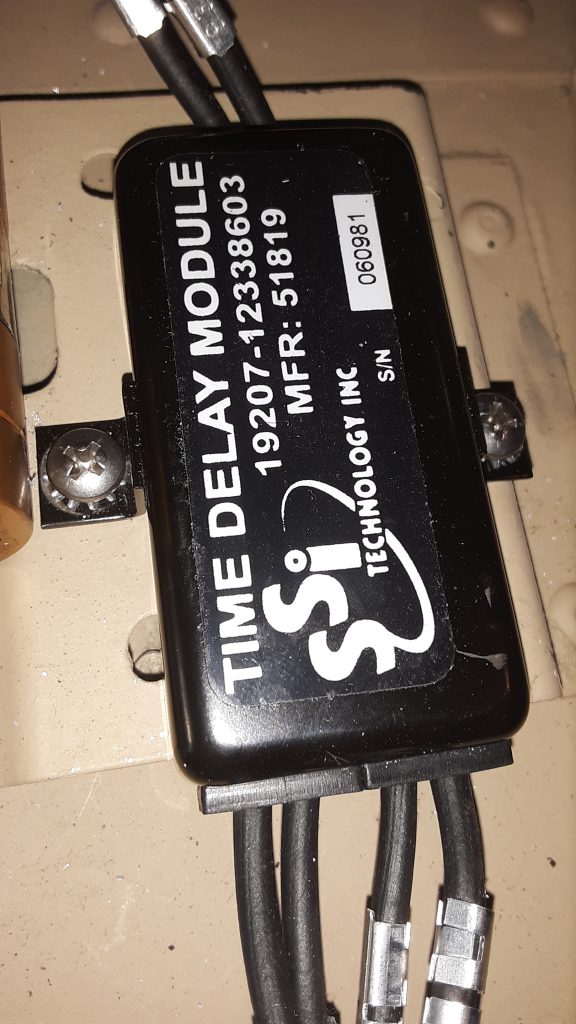
It is not uncommon, when replacing the Time Delay Module, to encounter stripped mounting holes. This is primarily because the mounting surface is aluminum, and people often overtorque the screws anyway. We attempted to use #10 sheet metal screws to mount the Module, but there was insufficient material to hold the screw.
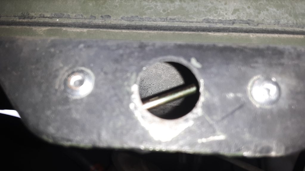
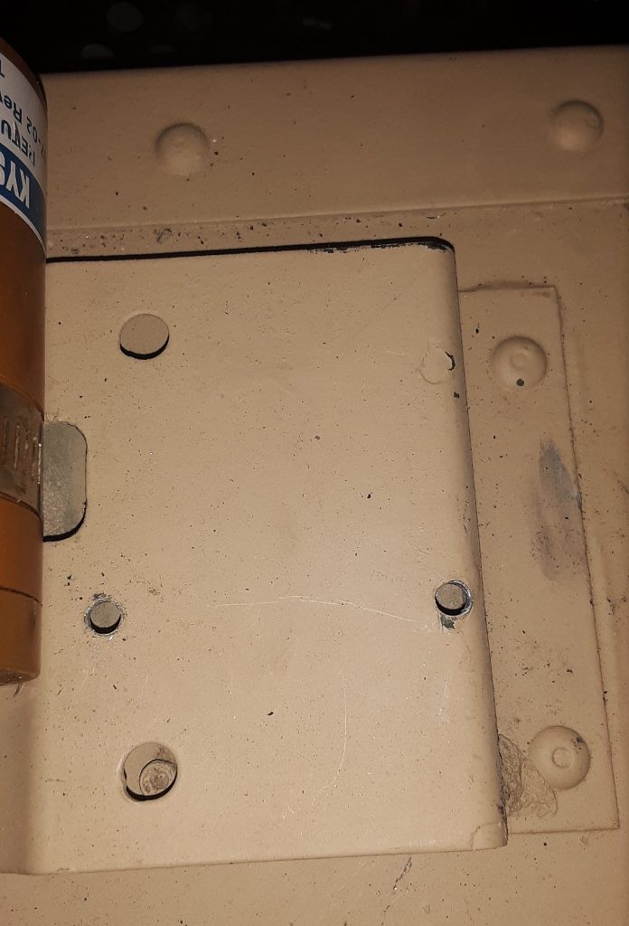
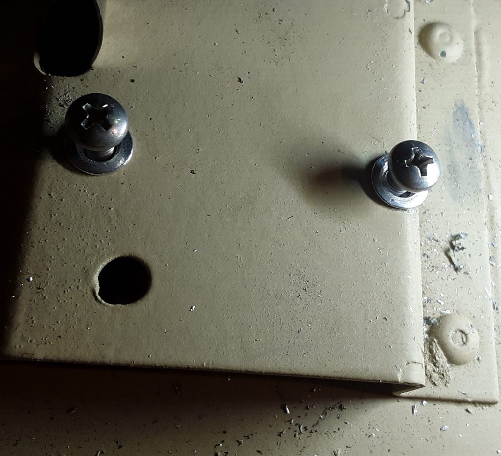
We initially attempted to use 10-32 x 1/2″ flanged screws with washers and nuts on the underside:
As you can see, the rearward screw cocks sideways. Although functional using the nuts on the backside, it was extremely difficult to accomplish, and would not be “user-friendly” when and if replacement was necessary. We removed the Module and decided to use rivet nuts (“nutserts”).
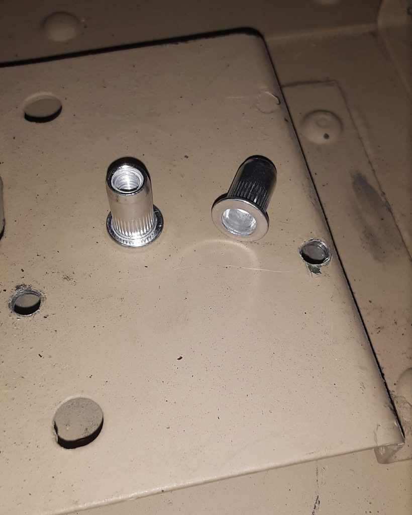
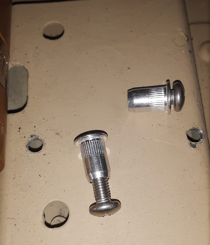
We intend to use 10-32 x 1/2″ screws, and acquired 10-32 rivet nuts intended for thin or sheet metal. The holes need to be drilled out to the outside diameter of the rivet nut.
Next, confirm the rivet nut is threaded correctly by inserting the screw into the rivet nut.
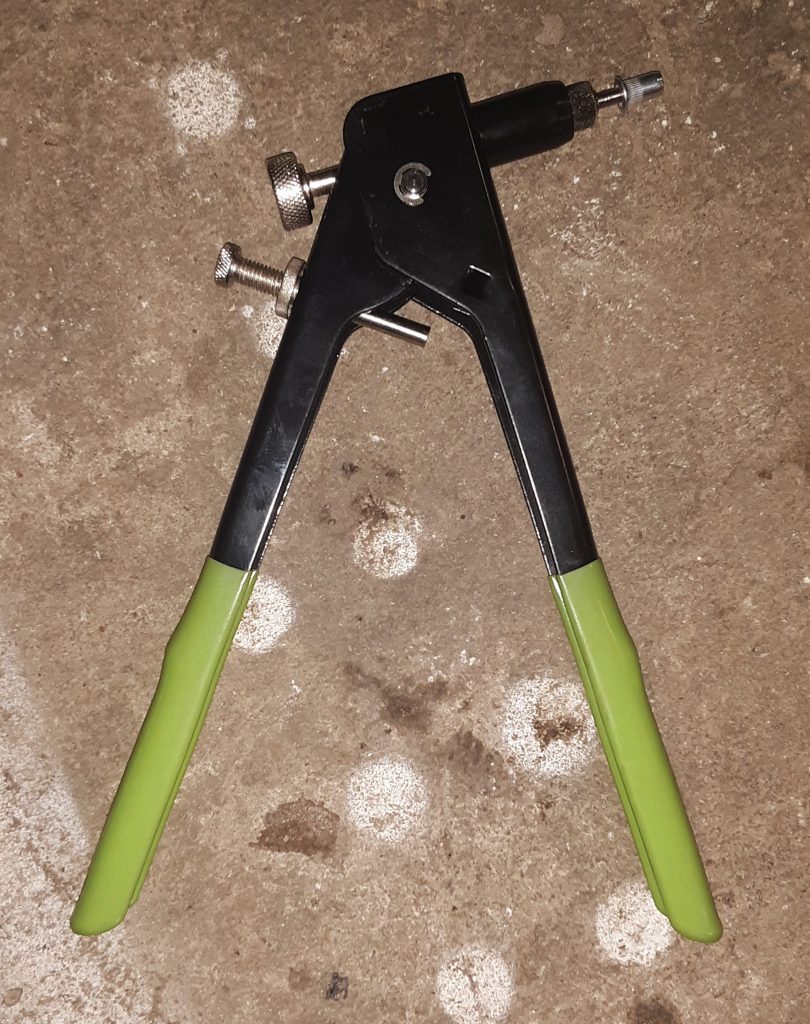
Next, thread the rivet nut onto the rivet nut gun and crimp into the drilled holes.
Once again, thread the intended screw into the crimped-in rivet nut to confirm threads are undamaged.
For final installation, we installed stainless steel screws and placed star lock washers to ensure they will not back out during operation.
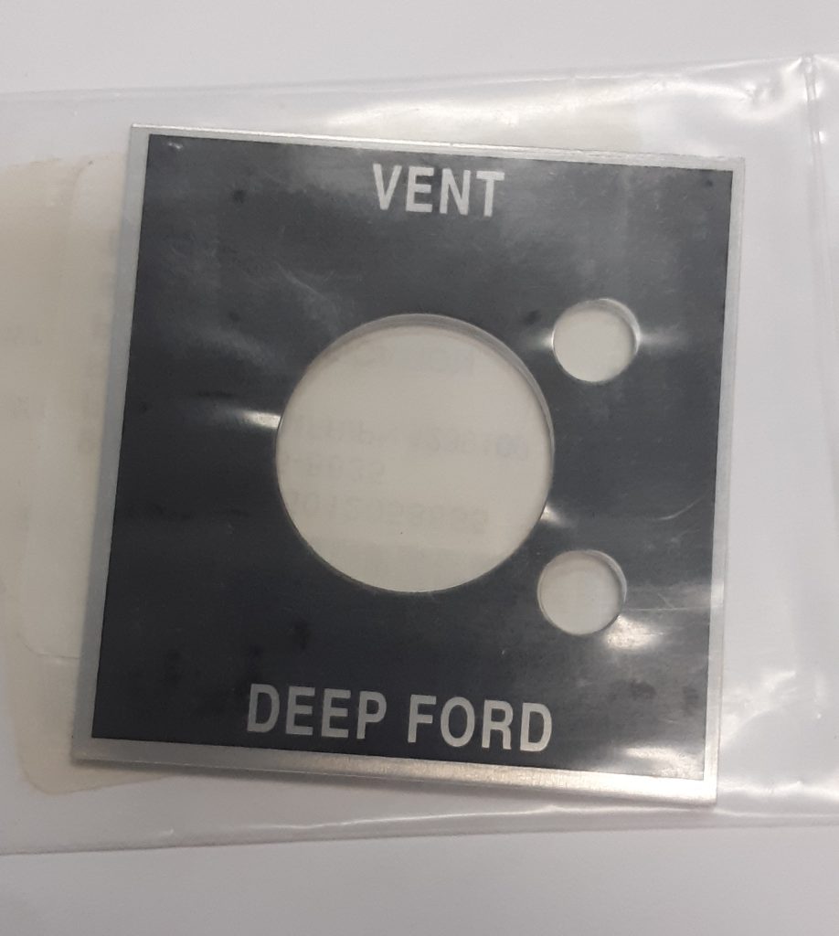
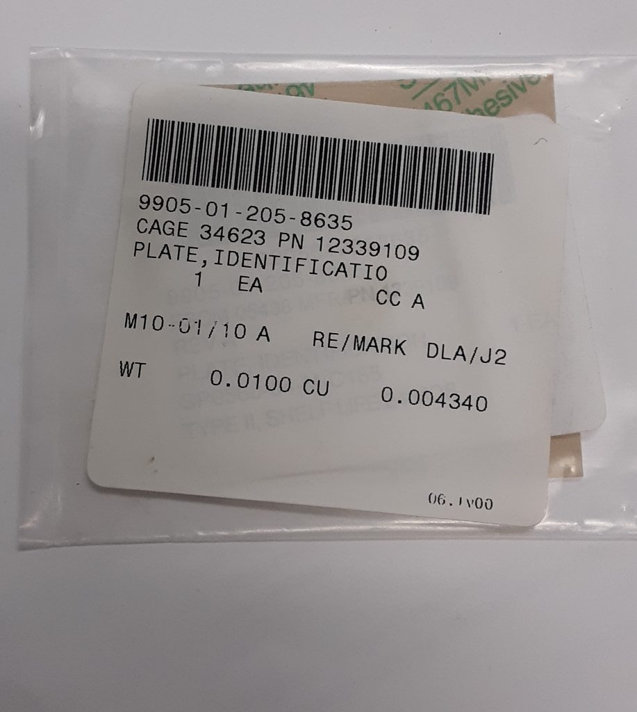
Although not necessary for a serviceable vehicle, generally replacing a worn or missing instruction plate is a worthwhile endeavor. The left picture shows the face of the plate that goes over the fording valve handle. The right picture shows the NSN of 9905-01-205-8635 [9905012058635]. It also appears to have an AM General P/N of 12339109
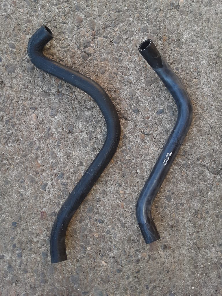
Left side, hose 4720-01-196-1636 designed for early version; Right side, hose 4720-01-360-2380
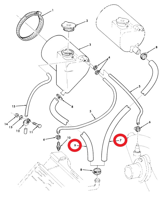
As our M1038 was an extremely early version, we assumed it would use the hose for the earlier version 4720-01-196-1636 [4720011961636] (Fig. 27, Item 7). However, we apparently had a later version tank 2930-01-256-5350 [2930012565350], so we required hose 4720-01-360-2380 [4720013602380] (Fig. 27, Item 9).
We note that we installed the hose intended for the earlier tank and could have simply cut off the excess length. However, there is a slightly different bend that gave us some concern about clearance with the radiator side shield. (After we installed the side shield, however, it was clear that cutting the earlier version hose would clear)