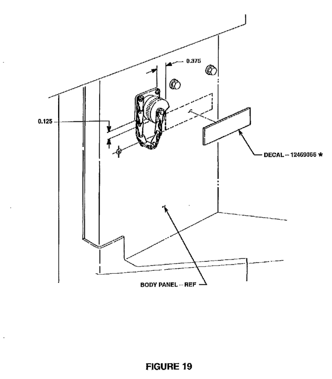
After installation of the 10,000 lb. winch, we went back to ensure all proper warning and instructional decals were applied in their proper places.
The instruction manual calls out 12469066 [ 7690-01-474-5928 / 7690014745928; Mile Marker 983-0021] being applied near the winch controller connector. Unfortunately, we did not receive that decal in our installation kit. Additionally, we were unable to locate an image of the decal, or even what it warned of.
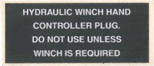
Ultimately we were able to purchase the decal from Kascar, LLC who had several in stock. We purchased additional decals in the event we need them in the future, or were required to reproduce or make a similar decal for future installs. Below is a scan of that sticker for reference to the text included on it.
12469066 / MM 983-0021 / 7690-01-474-5928 / 7690014745928
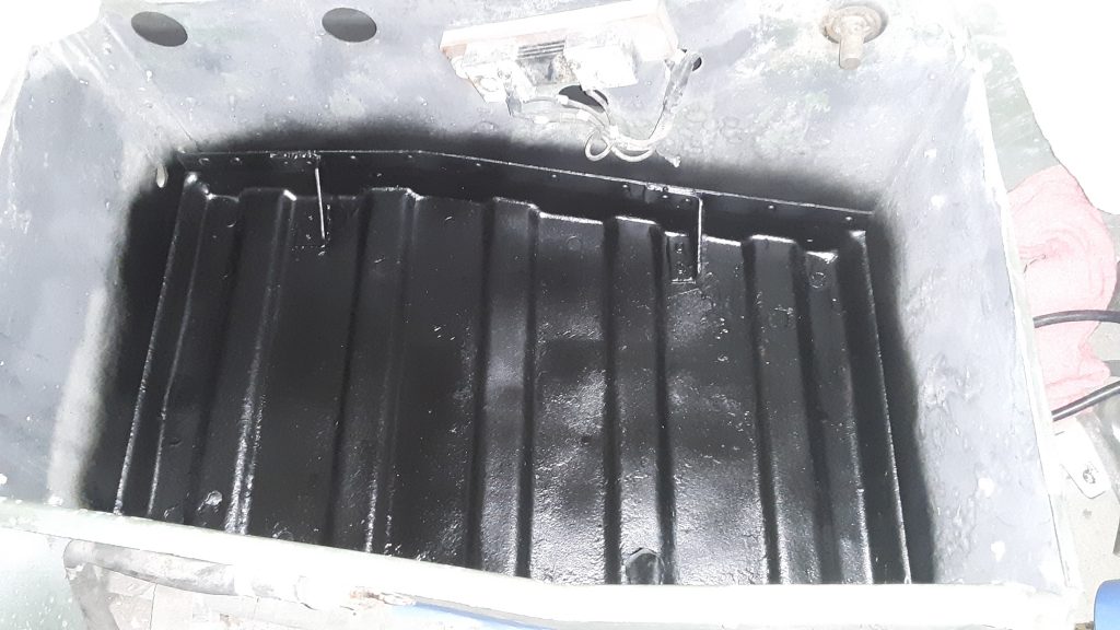
As discussed in a previous post, We removed the shunt and coated the entire interior of the battery box with the rubberized undercoating to protect the aluminum against corrosion from battery acid.
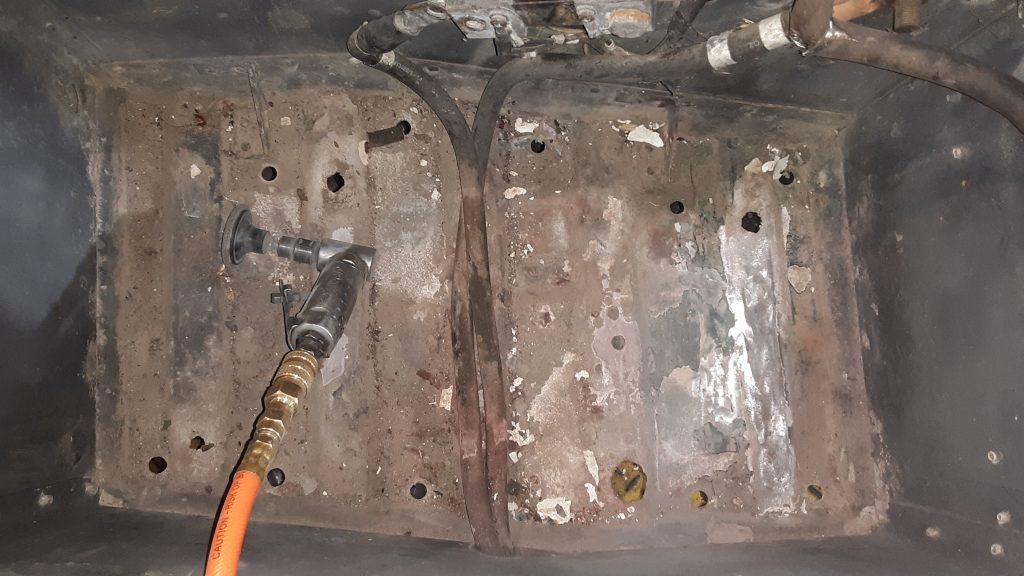
In preparation for installation of two new 6TL batteries to power the M1038, we removed the battery hold downs and tray to see the extent of acid damage on the aluminum.
Although there was extensive corrosion evident, the CARC seemed to provide a lot of protection from the acid. After spending considerable hours scraping, wire brushing and using a “scruffing” pad on a small air grinder, we applied several passes of baking soda and water to neutralize any remaining acid.
After thoroughly flushing and drying the surface, etching primer was applied and let dry. We debated about final coating and went with rubberized undercoating. This material is definitely acid resistant. And it appears that the box may have been originally coated with rubberized undercoating from the Marines.
We will next remove the shunt and mask off the entire battery box to be coated with the rubberized undercoating.
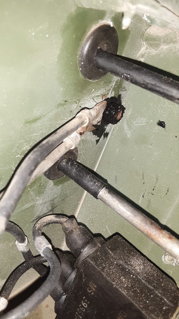
The HMMWV has a reputation for grounding issues. Poor grounding can cause faulty or unreliable gauge readings, and can also cause failure of components including the control box.
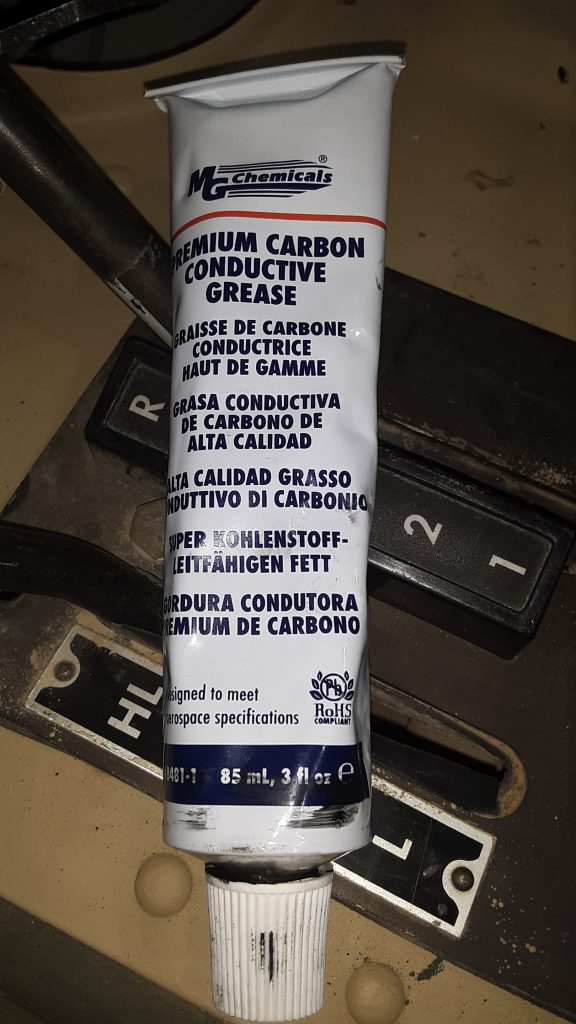
We removed and cleaned all connections, and liberally applied carbon grease to all contacts to ensure the best possible connection. After this photo was taken, excess carbon grease was wiped off. This compound is highly conductive, and it is unwise to not clean up after a sloppy application.
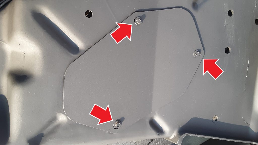
When installing splash shield supplemental armor 9515-01-189-9728 [9515011899728] to the left hand splash shield, it is required to eliminate the access cover 5340-01-457-0459 [5340014570459] by removing the three screws 5305-00-115-9934 [5305001159934] (MS51849-55) indicated by the red arrows that attach the access cover to the splash shield.
Failure to remove the access cover when installing the supplemental armor will result in an incorrect fit, and possibly damage to the splash shield. Additionally, the access cover cannot be accessed because it will be blocked by the armor.
A HMMWV radiator, as well as the cooler, are rather expensive. Although the splash shields do offer some protection from rocks and debris thrown from the front wheel, they are probably limited to offering protection against little more than water.
Plastic tends to break down over time and exposure to elements. Although our side shields appeared serviceable, we opted to install supplemental armor to provide additional protection.
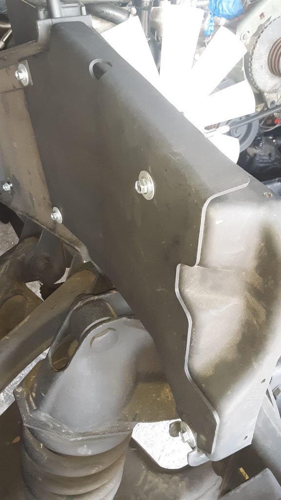
The picture below shows the RH side supplemental armor 2510-01-189-9744 [2510011899744] installed over the side shield.
There are two additional side shields available for each side. The standard (or basic) radiator shield for the RH side is 2510-01-185-7946 [2510011857946]. The supplemental armor is a little over twice as thick, and is called out as “armor plate.” The basic plate appears to be manufactured from mild steel.
Supplemental armor for the LH side is 9515-01-189-9728 [9515011899728], whereas the basic is 2510-01-185-3107 [2510011853107].
We also updated and improved the fasteners attaching the supplemental armor to the splash shields.
In the picture above, we did utilize the 5/16-18 x 1″ self tapping screw 5305-01-253-2993 [5305012532993] called out for attachment to the air lift mount. However, the TM calls out for a 5/16″ washer over a 3/8″ washer. We instead chose to use a 5/16″ lockwasher and a 5/16 x 1 1/8″ fender washer. In our opinion this offers an esthetic improvement as well as ensuring that the load is evenly distributed. We are unsure as to why this was not done instead of stacking two different size washers. Regardless, our substitution is appropriate.
On the other positions that did not call for a self tapping screw, we substituted 5/16-18 x 1″ “Wiz” bolts and nuts (also known as serrated flange) in place of the regular bolts called out for in the TM. Because of the serrated flanges, these act to some degree as a lock washer, and the flanged head helps distribute load on the inner side of the splash shield. Also, again we used 5/16 x 1 1/8″ fender washers in place of the stacked washers called out.
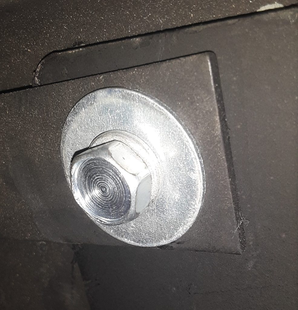
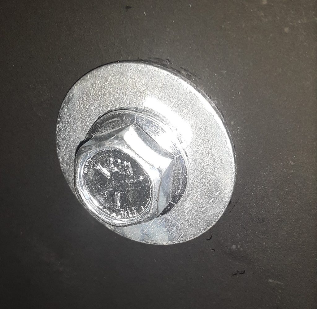
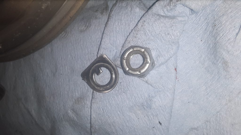
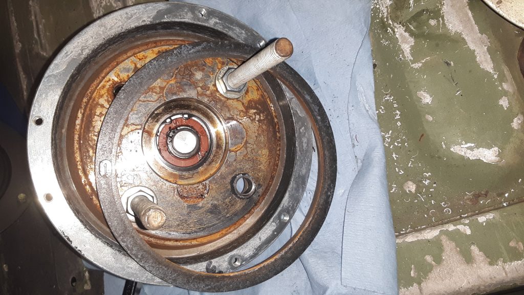
The first step (once the fan clutch has been removed from the engine) is to remove the lock nut 5310-01-194-0481 [5310011940481] and locking tab 5310-01-189-8468 [5310011898468] from the face of the cylinder assembly 2930-01-189-1744 [2930011891744].
Self locking nut and locking tab from front of fan clutch
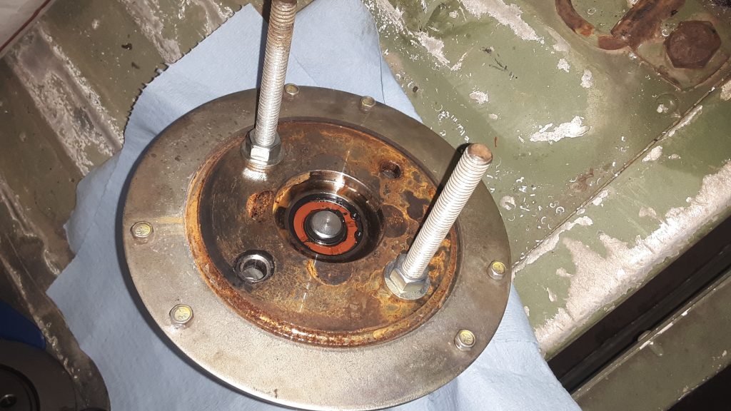
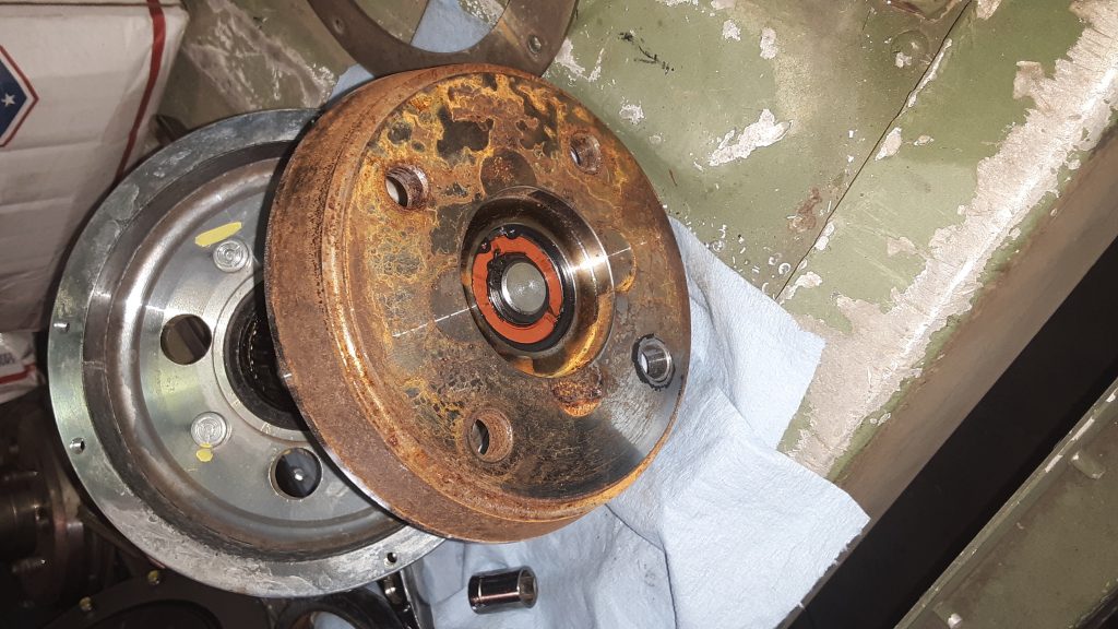
Next, install two 3/8 x 5″ (or so) bolts as shown below and tighten the shaft assembly 4079-38441-01 (no NSN) into housing assembly 4040-38442-01 (no NSN) enough to release the spring tension to remove the six capscrews 5305-00-052-6456 [5305000526456] holding the back plate on . Remove the backing plate. Do not, under any circumstance, remove the backing plate screws without a method (such as the bolts indicated in the picture) in place. There is a spring under pressure and failure to properly restrain it can lead to serious injury or even death.
Once the backing plate is removed, the clutch lining 2930-01-189-8643 [2930011898643] can be removed. It is not uncommon to stop at this phase, if the problem was that the fan wouldn’t DIS-engage because the lining had “frozen” to the shaft assembly. If not being replaced, the lining can be cleaned up using emery cloth or similar. The clutch surface of the shaft assembly can also be polished in this manner.
Friction lining removed, shaft assembly under spring tension (held safely by 3/8 bolts).
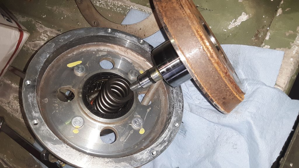
Once the spring pressure is completely relieved by slowly releasing tension on the safety bolts, the safety bolts can be removed. Inspect the inner bearings as well as the Torrington-style bearing and seals. Replace any damaged parts.
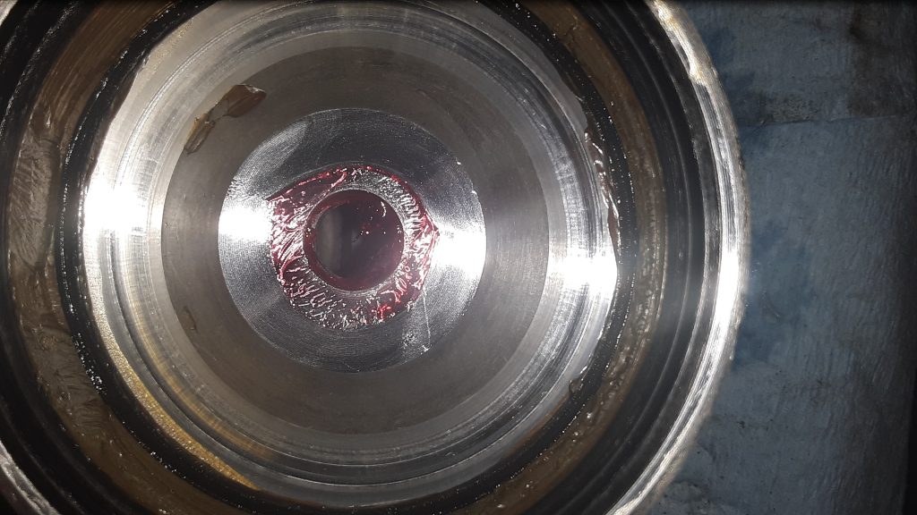
The below view shows the spring, seal and inner bearing. Ensure all O-rings are serviceable, and that the bearing surface on the shaft assembly is not damaged.
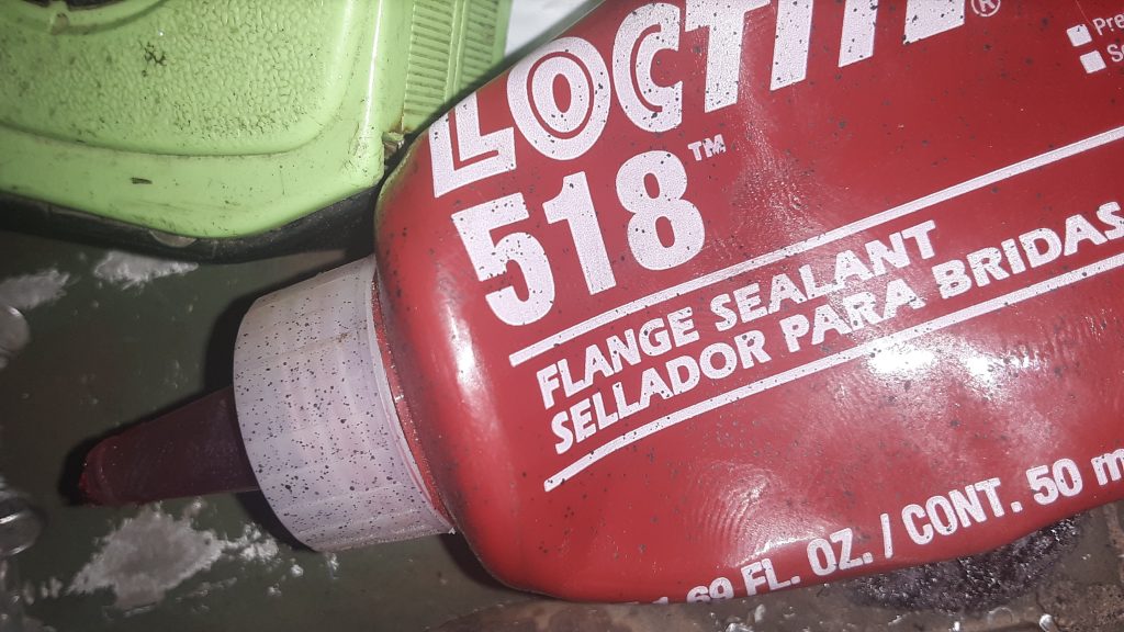
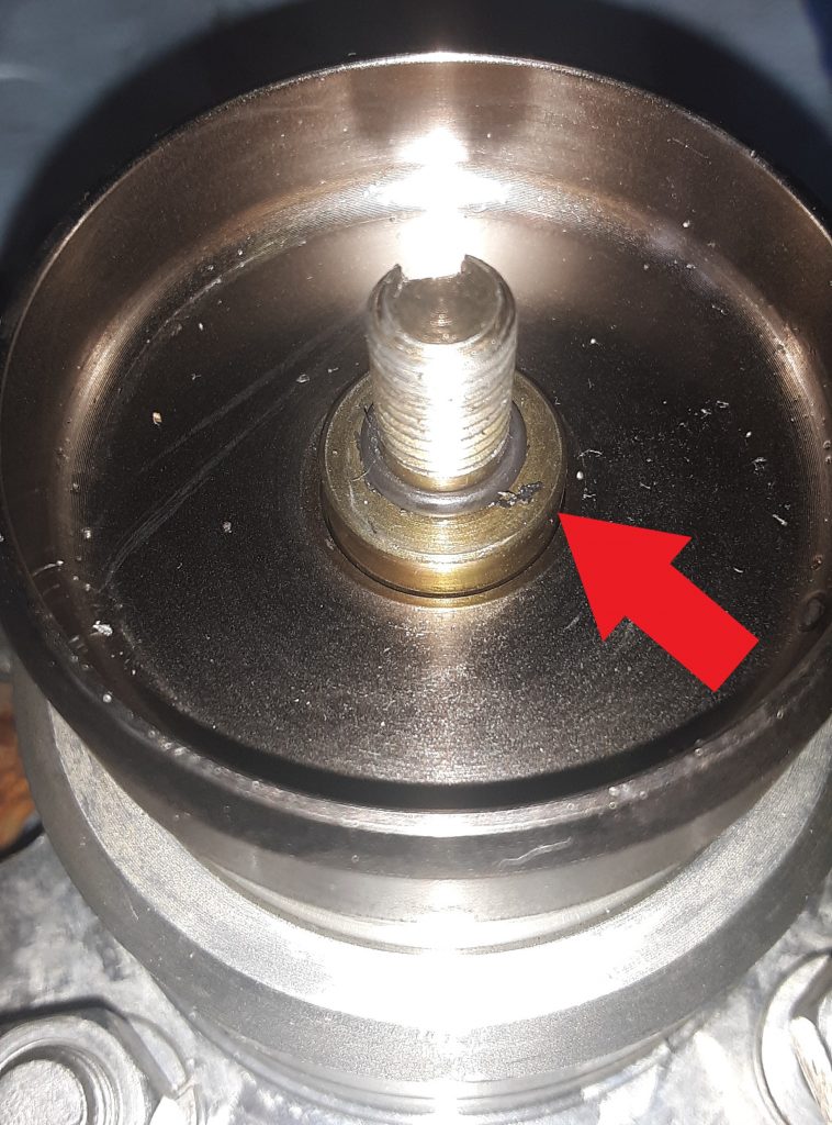
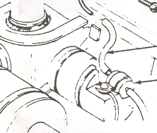
On reassembly, there is often leakage at the front O-ring, even when a new O-ring is used. Because of the likelihood of leakage, we recommend use of Loctite® 518 (or similar) on the sealing surface indicated by the Red Arrow in the picture below, as well as the corresponding location.
Reassemble the entire unit as it was disassembled. Again, Use safety precautions during reassembly because you are putting a lot of potential energy into the spring as it is tightened. Improper assembly can potentially cause serious injury or even death. If you have any doubts, please refer this to a professional or person experienced in assembling spring loaded machinery.
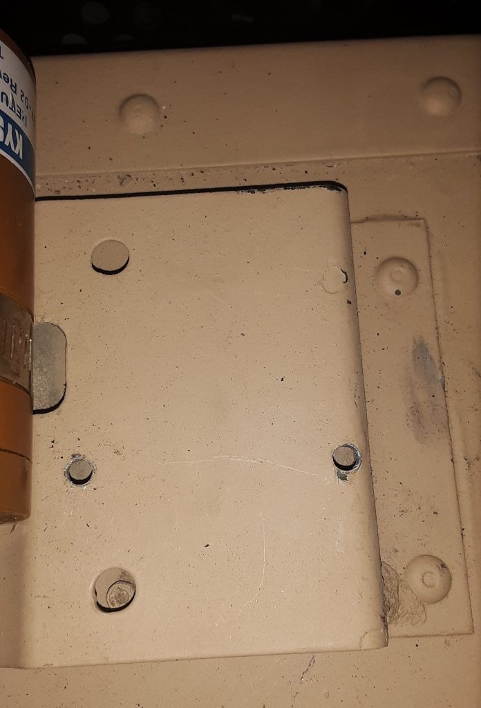
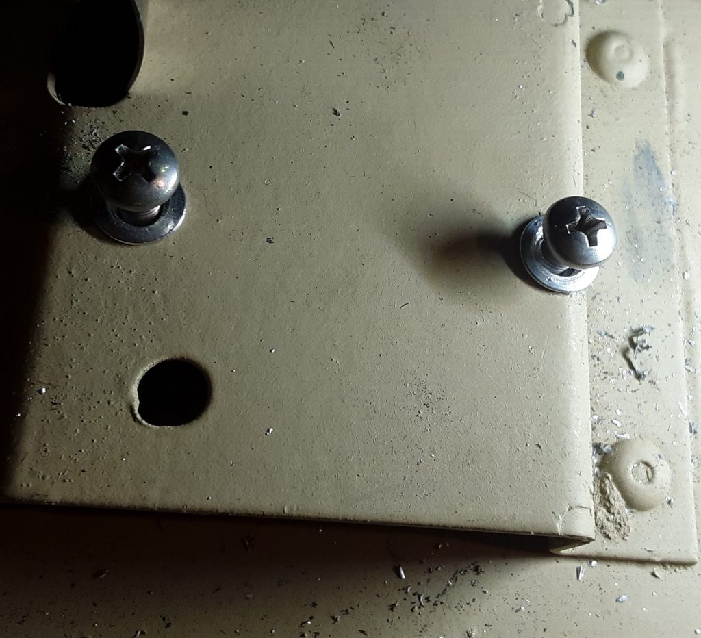
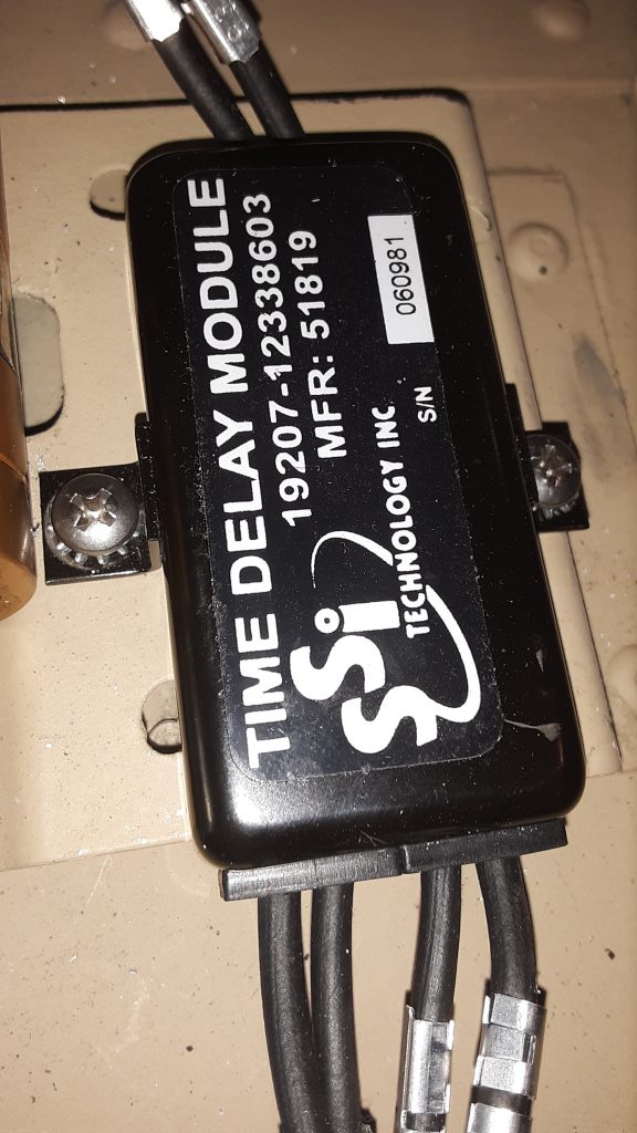
It is not uncommon, when replacing the Time Delay Module, to encounter stripped mounting holes. This is primarily because the mounting surface is aluminum, and people often overtorque the screws anyway. We attempted to use #10 sheet metal screws to mount the Module, but there was insufficient material to hold the screw.
We initially attempted to use 10-32 x 1/2″ flanged screws with washers and nuts on the underside:
As you can see, the rearward screw cocks sideways. Although functional using the nuts on the backside, it was extremely difficult to accomplish, and would not be “user-friendly” when and if replacement was necessary. We removed the Module and decided to use rivet nuts (“nutserts”).
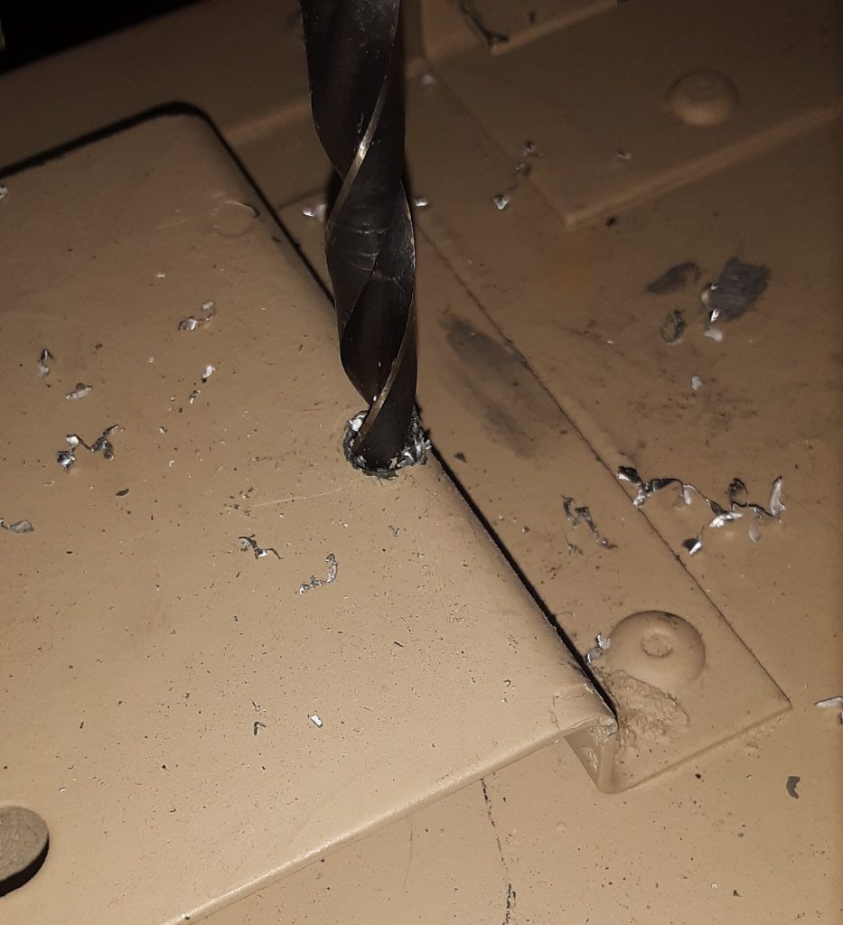
We intend to use 10-32 x 1/2″ screws, and acquired 10-32 rivet nuts intended for thin or sheet metal. The holes need to be drilled out to the outside diameter of the rivet nut.
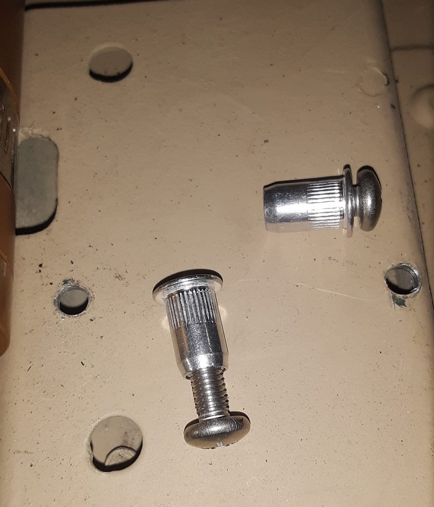
Next, confirm the rivet nut is threaded correctly by inserting the screw into the rivet nut.
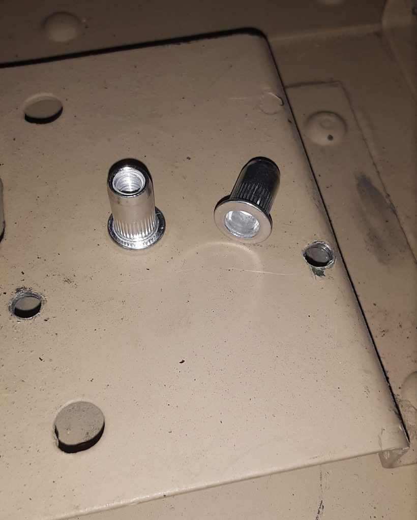
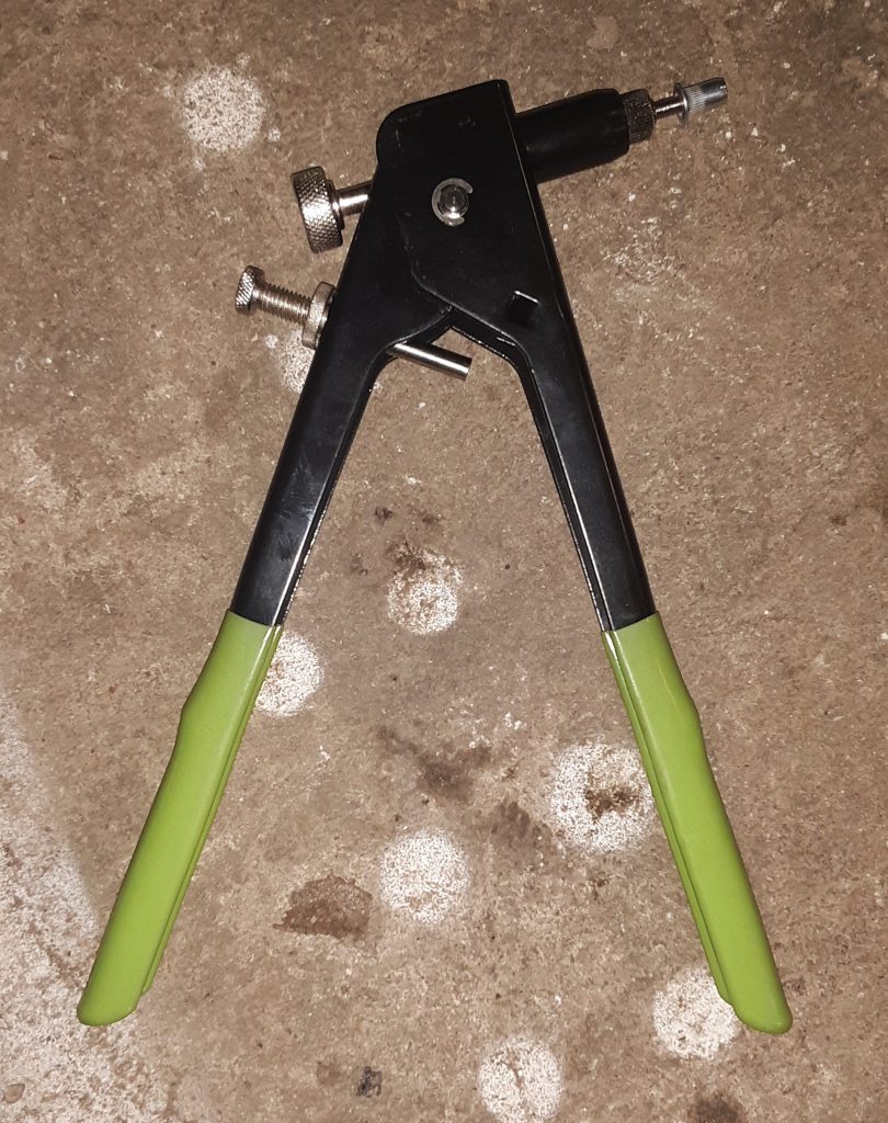
Next, thread the rivet nut onto the rivet nut gun and crimp into the drilled holes.
Once again, thread the intended screw into the crimped-in rivet nut to confirm threads are undamaged.
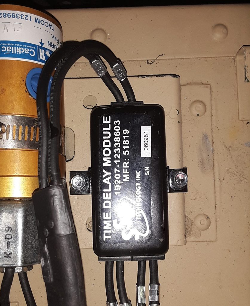
For final installation, we installed stainless steel screws and placed star lock washers to ensure they will not back out during operation.
As we discussed in an earlier post, Dexron III is what was called for in the Transfer Case, and use of Dexron VI has led to parts failure. As discussed, our research indicates that GM continues to recommend use of Manual Transmission and Transfer Case Fluid 88861800 for the transfer case.
As the picture indicates, this fluid is also marketed as AC Delco 10-4033. We used a Lincoln suction gun to fill the 242 transfer case. We had previously drained the transfer case to ensure no contaminants were present, and used just about 2 1/2 quarts to bring the fluid to the proper level.
Although we have identified fluids being marketed as “recommended for” Dexron III applications, we chose to use GM’s recommendation as we did not want to risk loss of a transfer case. However, we will likely use a “recommended for” Dexron III (H) fluid when we fill the transmission, and bleed out the cooler and winch.
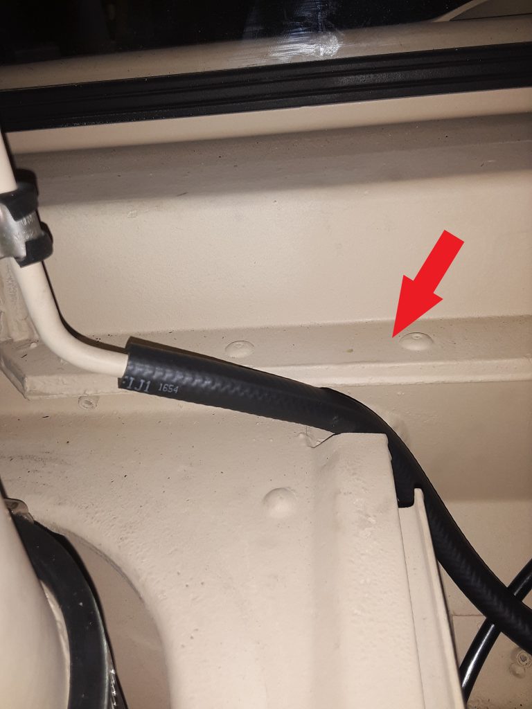
Hose is Figure 398, Item 30. (The Corbin clamp is not on the vent tube at time of photo)
The arrow in the photo above indicates the position where the vent hose leading from the fuel tank vent line filter 2910-01-210-5872 [2910012105872] (behind the surge tank) is to be placed for clearance when the hood is closed. Note a Corbin style clamp 4730-00-954-1251 [4730009541251] needs to be placed on the hose ends both where the hose attaches to the tube and to the filter.
The callout for this hose is for an 11″ length of CPR104420-2 (replaceable with 3/8″ air brake tubing, such as Eaton Synflex®). We instead replaced this with 1/4″ SAE J30R9 hose (which we consider a modern and equal substitute for RB1450-1-4IDX1-20D).
Our reasoning for using hose instead of tubing is based on a couple factors: First, it is called out as RB1450-1-4IDx1-20D (or equivalent) to connect the fuel tank vent line to the fuel vent line filter (See Figure 18, Item 6). We are of the opinion the hose leaving the vent line filter should be the same as the hose entering the filter, and that indication of tubing may be an error in the TM. Second, use of air brake tubing essentially requires a heat gun to soften the tubing enough to slide over the tube on the stack and bead on the filter itself. Although this can be accomplished, should field repairs be necessary, it essentially requires cutting the tubing, where the hose can be easily removed by loosening the Corbin clamps.
Note: the drawing indicating the vent line hose appears to be the same as the hose entering the vent, and does not appear to be tubing. Although this may be based simply on the artist, we are of the opinion that the hose leaving the vent should be the same as the hose entering the vent.
We note the installation instructions for the DWF kit also indicates the CPR104420-2. See http://www.hummerknowledgebase.com/driving/dwf.html (at Image 3), where is specifically calls out an 11″ length. (We do, however, note this document is extremely dated, as it calls out for use of Dexron II at Image 5). Dexron II was long ago deprecated: In 1993, GM released new Dexron-III fluid (GM Spec GM6417M and later GMN10055). As noted above, we believe the J30R9 hose is made from material superior to what was available during original engineering of the HMMWV. and stand by our recommendation to instead use J30R9 hose.
Although we have no way of knowing at this time, there may have been a UV (sun) resistance issue where the engineers preferred the air brake tubing over the hose for that reason. It may well be that the CPR104420-2 tubing has a greater resistance to breakdown that the RB1450-1-4IDx1-20D hose. However, we are around 30-some years since the original design, and materials have changed. We will monitor the J30R9 hose to determine if it exhibits any undesirable weathering characteristics.