As explained in an earlier post, we unknowingly attempted to install a later model fuel tank into an early model HMMWV. And despite difficulty in locating the correct tank, we were able to. It arrived today, and we intend to install it in the next few days.
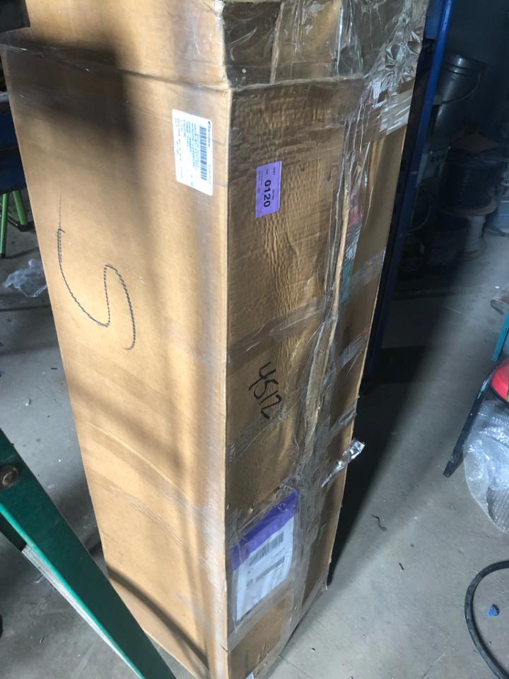
Boxed fuel tank 5582606 for early serial number HMMWVs with separate parking brake
As we install this tank, we will attempt to document and post any differences between this main fuel tank and the early tank.
We had purchased a fuel tank for our M1038, as well as the missing straps, fuel level sender and other pertinent parts, and were ready for installation.
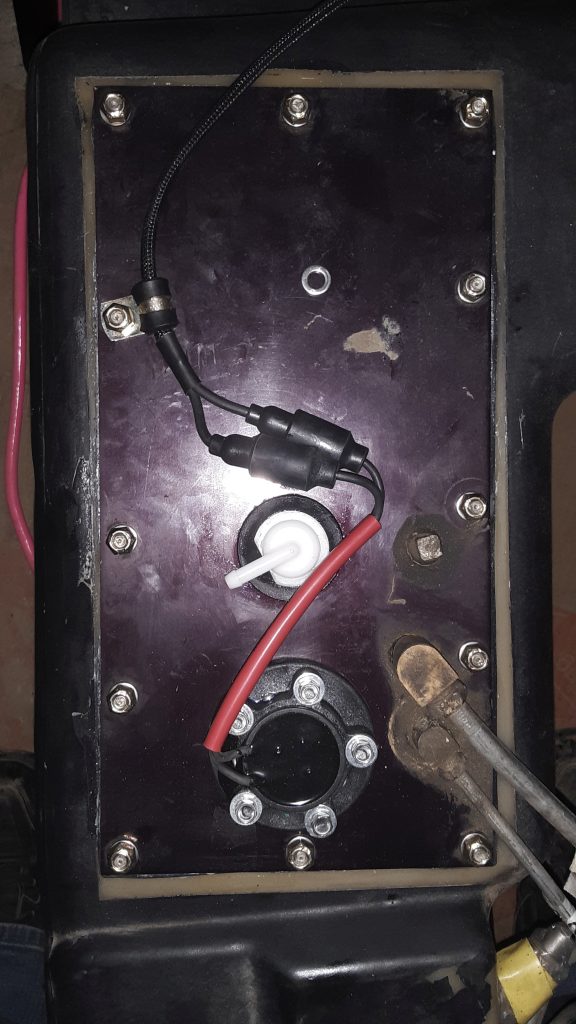
Top view of fuel tank ready to be installed
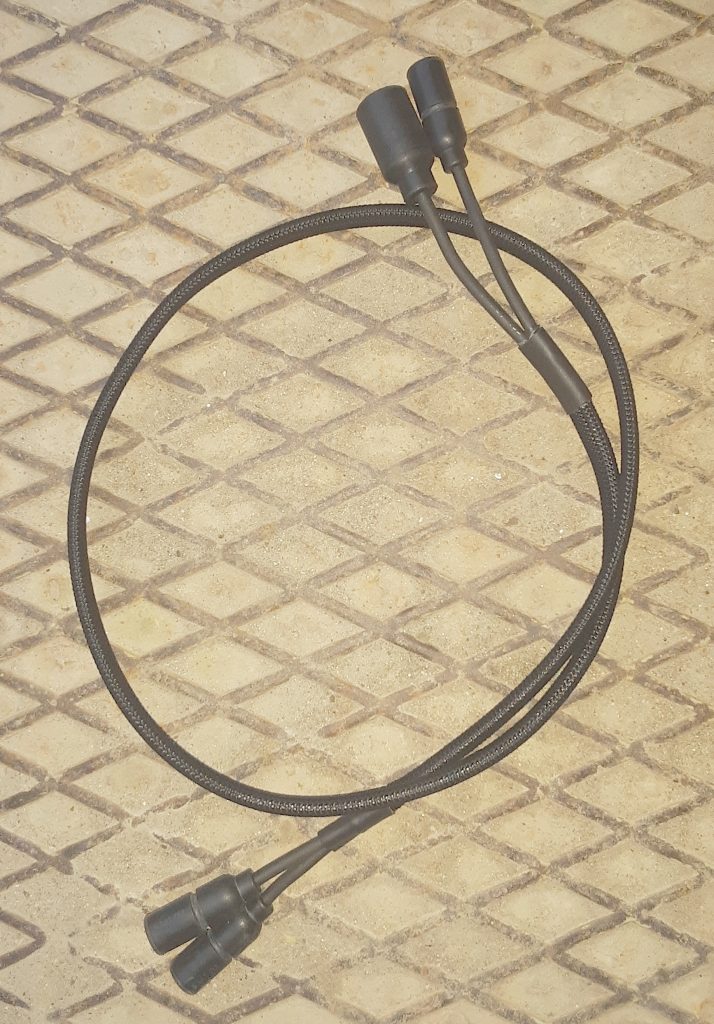
We were unaware, however, that the jumper between the fuel tank and the wiring harness was missing. So, using the correct Prestolite wire, wiring ends, and PET loom, we fabricated a replacement jumper. (Ensuring that it was made to military specifications).
UPDATE 3/ 24/2019: We fabricated the jumper at a 36″ length. As it turned out, the length could have easily also be made at 18″-24″ length. As it turned out, we cable-tied the excess to the fuel tank vent tube near the crossmember where the jumper connects to the harness. We suspect that should we have to remove the tank in the future, the extra length will prove “slack” to permit us to lower the tank without having to disconnect the jumper from the harness.
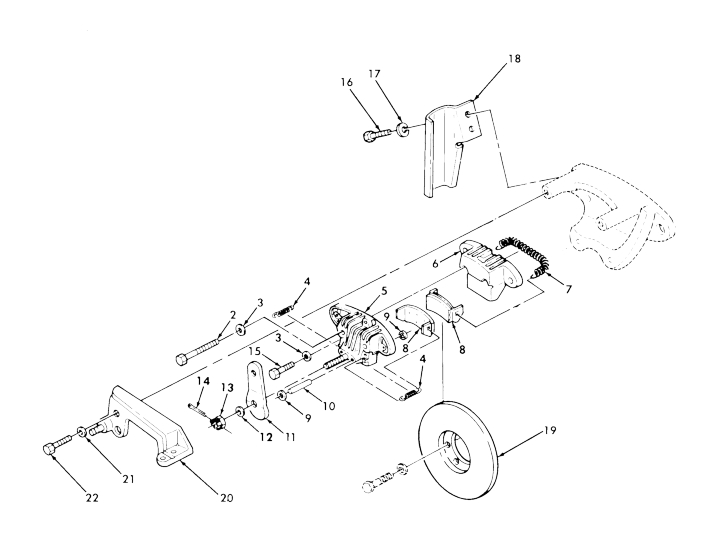
We were ready to install. Or so we thought. Even after removing the driveline, we found that we could not physically fit the tank into the area, as it hit the emergency brake caliper, rotor, and bracket.
We were simply unaware there was more than one main fuel tank. Our tank 2910-01-447-3911 [2910014473911] carries part number 12460105, and is easily located. As it turns out, we should have verified application through the UOC (Usable On Code) found in the parts TM in the far right side under description.
The UOC for a M998 is H13, whereas the UOC for a M1038 is H14. For practical purposes (other than differences between having a winch or not) either code would be accurate.
As it turned out, the NSN for the tank we had did not have the correct UOC, and we found the tank we required was part number 5582606, with no NSN provided for a part number. We simply had the wrong tank.
Through further research, we were able to identify a serial number split from 1 thru 44824, which uses the brake mounted against the rear differential on the driveshaft side. 2530-01-174-7441 [2530011747441].
We are well aware of operator complaints regarding this parking brake, but have found to often that operators attempt to adjust the brake from the brake handle adjustment (which is meant only to adjust for slack in the cable), and not properly adjust the brake from the caliper adjustment. We purposely chose to maintain this brake system because of our unit’s 4 digit serial number for historical purposes.
However, as noted above, we were completely unaware that maintaining this brake would require a fuel tank of limited availability.
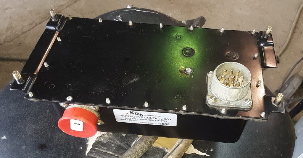
For our M1038, we obtained a mid-series control box, and a corresponding controller. The control box was in unused condition, and its connectors show indications that it has never been connected.
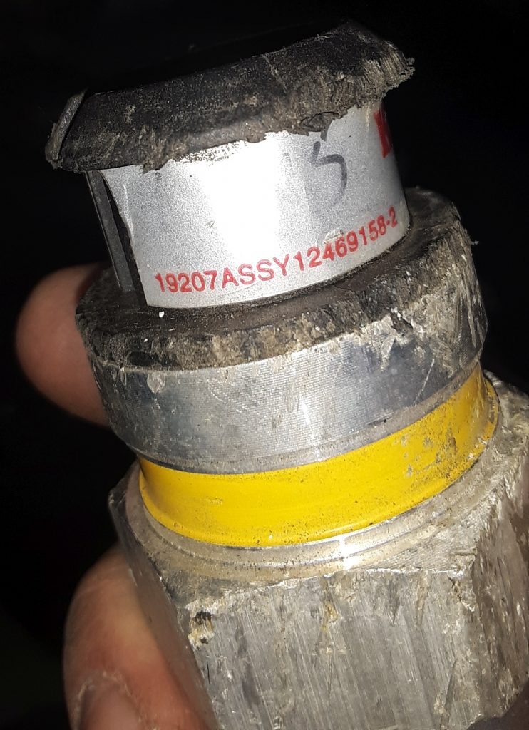
We located a controller that corresponds to the controller, but it had sustained some cosmetic damage.
Information on this controller 19207ASSY12446779 is scant. From what we can determine it was used on the M1113, and is similar to what was used on the M1114. (The M1113 used studs, as on this box, while the M1114 was threaded where the studs are).
It may also be referred to as a “silver label.” To make it clear, these are not EESS boxes. These boxes have been used on trucks up to the m115x, and are the generation between the old yellow/green label ones & the EESS. They are apparently a generation newer than the yellow label control boxes.
We have been cautioned that the operation of this box may make the “wait light” fail to light at higher ambient temperatures, but that is simply because it is not necessary to cycle the glow plugs.
Additionally, we have been cautioned that should a control box fail, there is a possibility that a vehicle fire may result. We will be installing a battery cut-off and will be testing the box before sending the vehicle out the door to reduce the potential for vehicle fire.
We have read good reviews on these boxes and that they are relatively reliable. However, if we note any issues we will reach out to an appropriate vendor for a newer generation control box and controller.
It seems that most people fail to understand the difficulty of
repairing or the time and expense to repair damaged transmission cooling
lines. Both the lines in our M1038 and from our new powerplant were
damaged, and unusable.
We could have just substituted hose for the lines. However, tubing is
far sturdier, and rated for higher pressures. Consequently, tubing is
less likely to fail than a long length of hose. Arguably, there is some
cooling effect to be accomplished just from the +/- 20 feet of line.
We determined that it would be virtually impossible to install
factory cooling lines without removing the cooling stack and possibly
even the powertrain. As a result, we used 3/8″ brake tubing and made our
own.
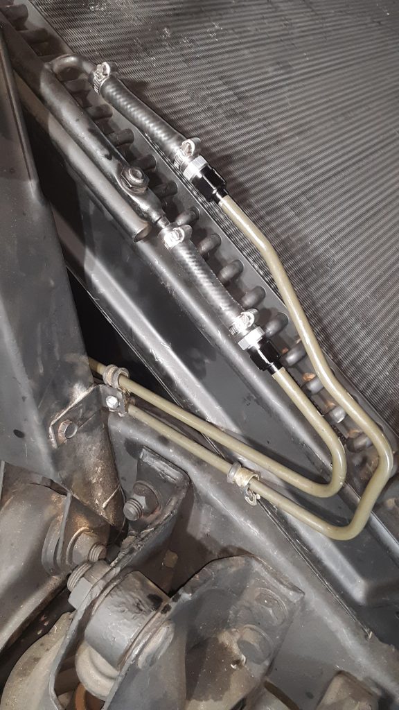
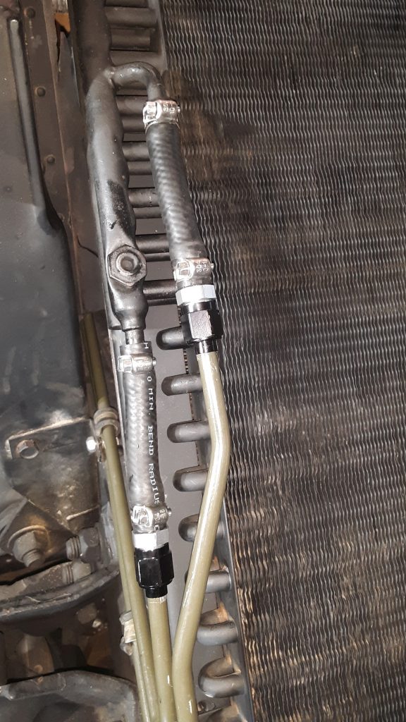
Custom fabricated transmission cooling lines to cooler (new cushion clamps are on order)
We fabricated our cooling lines in two pieces (each line) that joins at the frame near the idler arm. This allowed us to have the complex bends on the front section, and allows for it to be somewhat easily installed. We do not have a 3/8″ beading tool — If we did, we would simply have beaded the ends. However, using a Ridgid 41162 377 flaring tool (which provides the proper 37 degree angle for AN fittings) and used Russell -6 AN tube sleeves and nuts to connect an AN to 3/8″ hose barb. This ensures a leak-free connection.
Although the transmission pressure through the cooler only reaches a
maximum of 30 p.s.i., we were still concerned about preventing leaks
between the hose and the tubing without having a bead.
Although the AN connectors are not cheap, we already owned the Ridgid
flaring tool, and the cost of the fittings was considerably less than a
beading tool.
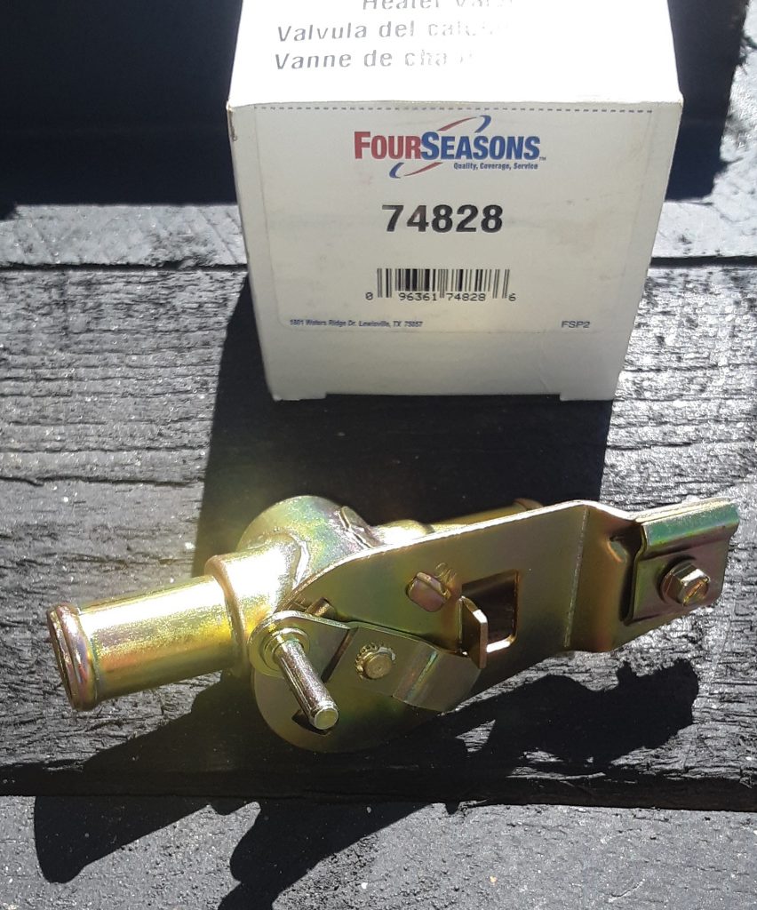
The Heater Control Valve 4820-01-189-2107 [4820011892107] (AMG 12339966) was missing from our vehicle. We researched the different aftermarket valves available and were able to locate a replacement: Four Seasons P/N 74828.
This appears dimensionally identical to one in an M998:
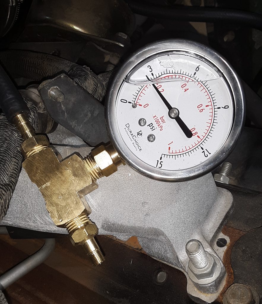
In order to confirm that all Deep Water Fording (DWF) vent lines, transmission seals, differential seals, etc are sealed, a leak down test is required.
Pictured above is a leakdown tester we assembled. We used a 1/4″ NPT brass tee, a 1/4″ NPT x 1/4″ hose barb, a 1/4″ NPT x Schrader valve, and a low pressure gauge (0-15 p.s.i.).
You may note that we used a glycerin-filled gauge. A glycerin-filled gauge adds a level of dampening in an application where shock-loading frequently occurs. It is unnecessary for this application, however the cost was only slightly higher than a non-filled gauge. Of note, filled gauges often have a small brass plug mounted in rubber to allow you to zero the gauge out if atmospheric pressure has raised it from zero.
WARNING AND CAUTION: We highly recommend using a hand pump, such as a bicycle tire pump. Should you put excessive pressure into the system while testing, it is highly likely that you will “blow out” seals, and potentially damage seals in the engine, transmission, gear hubs, and differentials. It takes a very little amount of air to reach 2 to 3 p.s.i., and even use of regulated air may provide a “burp” of air at a pressure sufficient to dislodge or destroy seals.
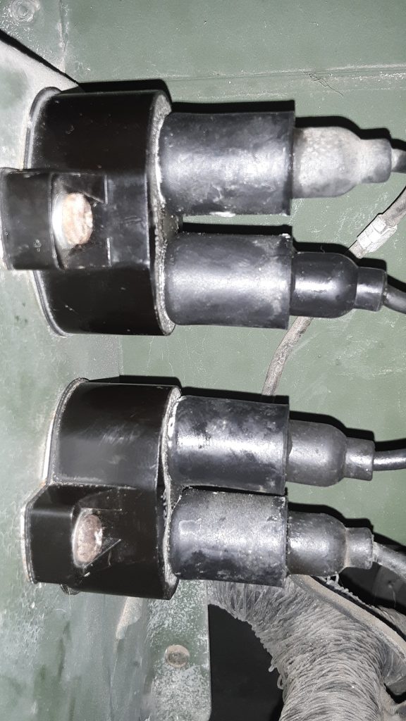
As the breakers currently mounted in the HMMWV are around 30 years old (and have likely gone through countless fordings), we opted to replace them.
Newly installed 15 amp Klixon circuit breakers
These circuit breakers are “Klixon” style 15 amp breakers. The callout in the Parts Manual for these units are 5925-01-430-2318 [5925014302318]. However, this number seems to be obsolete. We were able to locate identical specification breakers under 5935-00-026-4767 [5935000264767]
These breakers have the same external dimensions and the same amp rating as the replaced breakers. The only difficult issue we had is that two of the connections would not release, and had to be replaced.
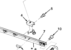
The screws attaching the bows to the side rails (Fig. 321, Item 6) calls out as 5305-00-059-3659 [5305000593659] with a general fastener number of MS51958-63 is essentially a 10-32 x 1/2″ pan head screw. Although we feel a standard 10-32 screw would be sufficient, we were able to source a number of the actual fasteners designated MS51958-63 at around the base price of the fastener from major vendors.
Although it is highly likely that a standard 10-32 screw would suffice in this application, we feel that use of the correct military fastener may give a slight performance advantage in both strength and corrosion resistance.
Of note, however, the fasteners we acquired indicate they are stainless, which is generally of a strength equivalent to a Grade 5 bolt. (of course, this depends on the type of stainless). We believe the vendor has mistaken plated fasteners as stainless. The packaging of the fasteners state they are MS51958-63. We have not reviewed the specifications of this fastener, but are of the opinion that even if stainless, they should suffice for holding the bows to the side rails.
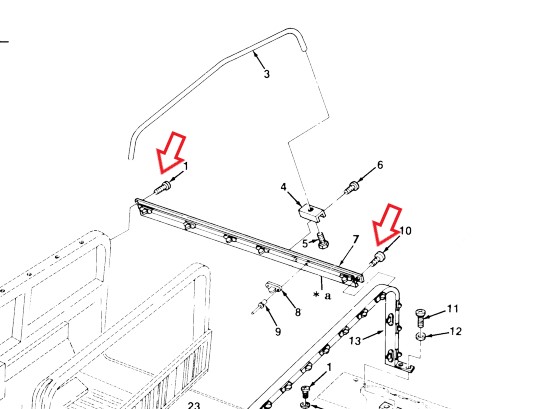
The screws at the front, middle, and rear of each rail are called out by different part numbers in the TM. The front screw (#1) 5305-01-210-6249 [5305012106249] with a manufacturer P/N of PL25D02P12 was not locatable.
The screw at the rear of the rail (#10) 5305-01-117-3396 [5305011173396] was similarly unlocatable, however we were able to locate this screw by its manufacturer P/N of NAS1635-3LE12. This is essentially a #10-32 x 3/4 screw. However, this has pre-applied locking compound. Additionally, we surmise this screw probably has a higher tensile strength than a standard 10-32 screw as it is an aircraft fastener.
As for the PL25D02P12 fastener called out for the front connection, at least one vendor (Kascar/real4wd.com) lists the NAS1635-3LE12 as an interchange. (at time of post, searching for the PL25D02P12 fastener comes up as NAS1635-3LE12) See: https://real4wd.com/store/catalog/search.aspx?keywords=PL25D02P12
In other words, we are comfortable that since both fasteners specifications are as a self-locking 10-32 x 3/4″, that use of the NAS1635-3LE12 is proper. There are apparently 50 in a box, and we have ordered 4 boxes to keep in stock.
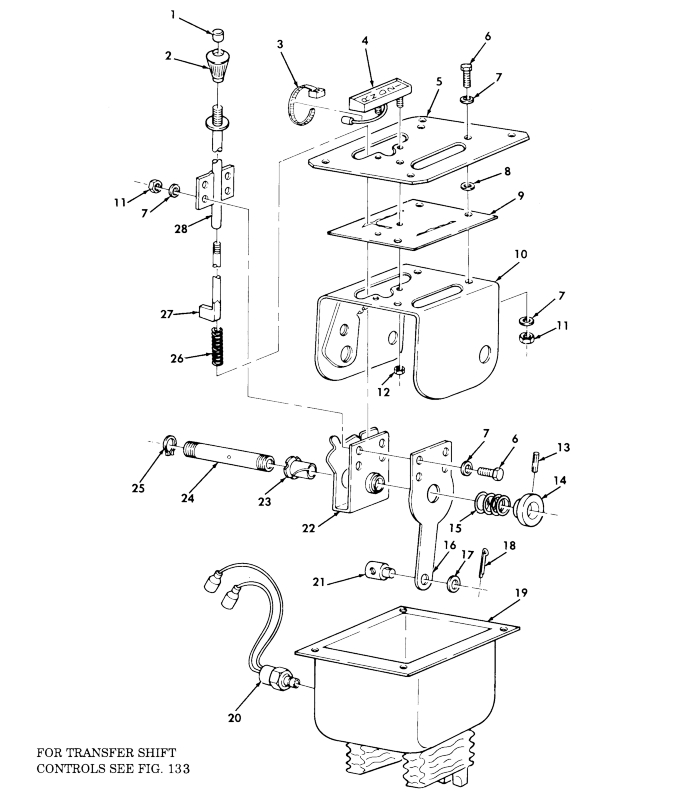
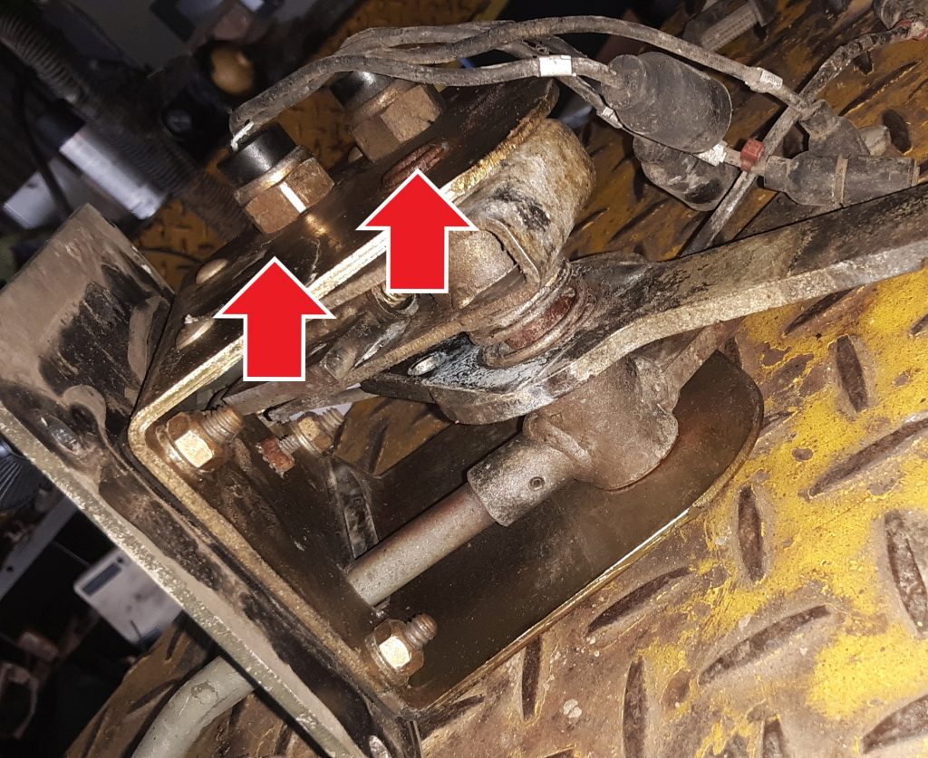
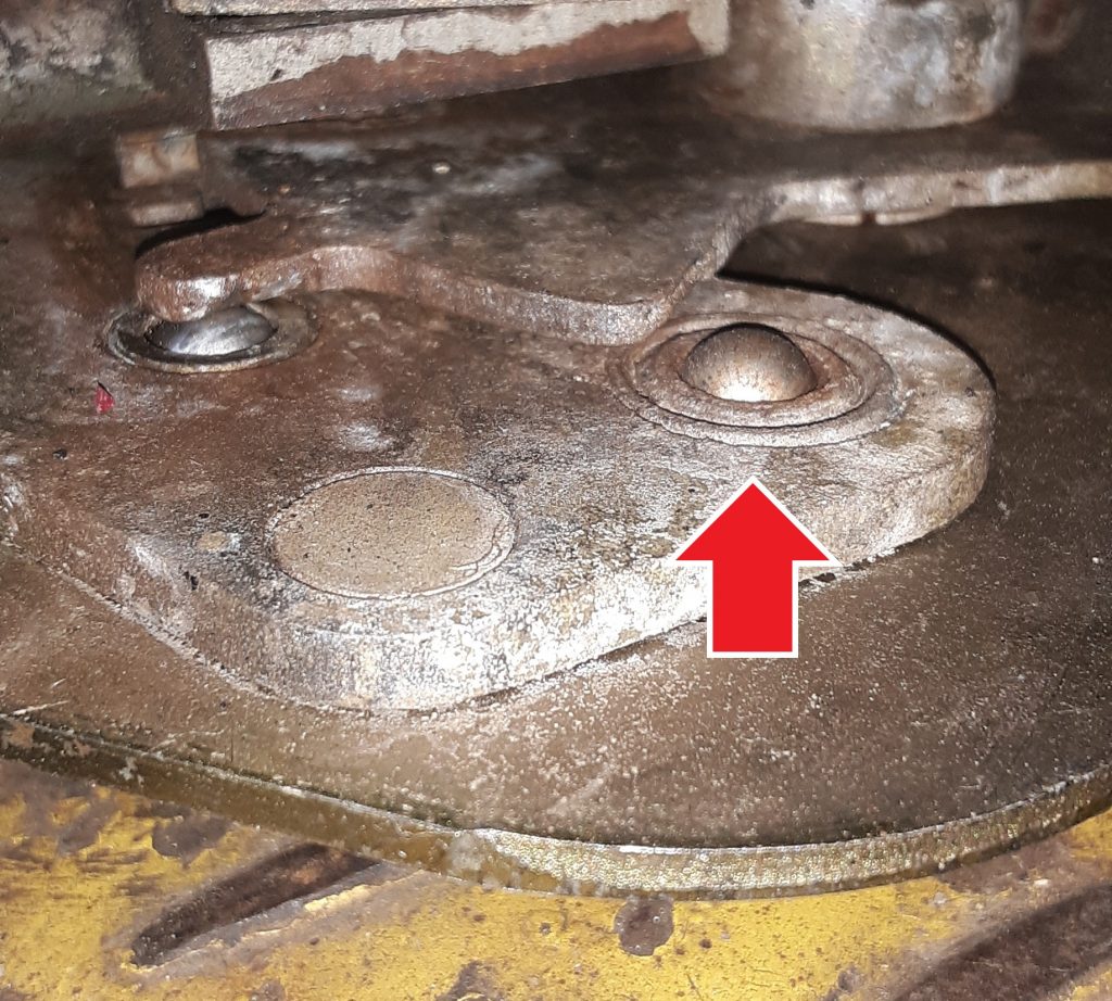
The transmission shifter in our M1038 was frozen, in that the release button could not be depressed to release the shifter. Additionally, the lever 2520-01-189-1064 [2520011891064] (Fig. 99, Item 16) was broken at the connection point. After removing the entire assembly, we noticed that this was an atypical shifter in that it had not only the safety switch 2920-01-249-3492 [2920012493492](Fig. 99, Item 20), but also a reverse light switch (not shown in diagram).
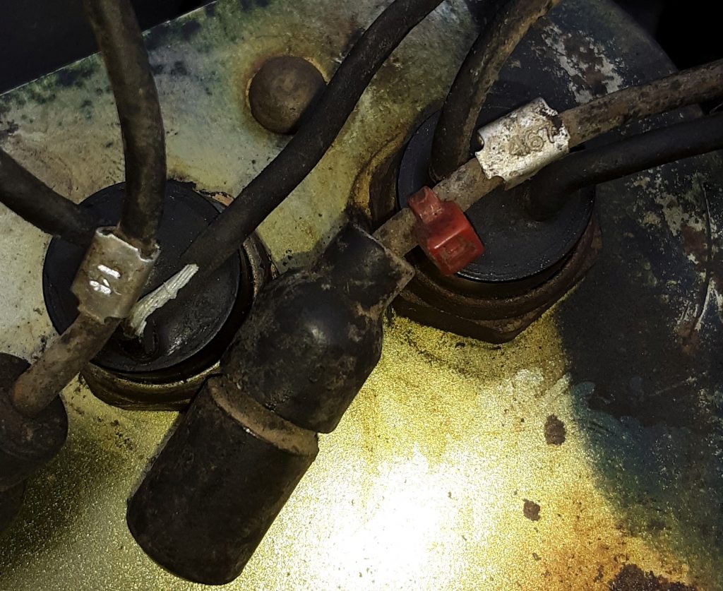
Shifter showing neutral safety switch and reverse light switch. Reverse switch is the right arrow.
It is our current understanding that the reverse light switch was used only on Marine HMMWVs, but that it is also desirable for on-road civilian use in states that require a functioning reverse light. The lead from one of the wires was 467 (whereas the neutral safety is 14). Of note, the hole for the reverse switch appears to exist in all of the housing assemblies (Fig. 99, Item 10). (See diagram). Of further note, the switch appears to be the same as the neutral safety other than there is a bushing installed to allow the smaller switch to be installed in a larger hole
From this, it appears that a reverse light switch can be installed in any of the earlier shifters. Once we identify the threaded bushing dimensions, we will post it. It seems relatively difficult to source the reverse light switch as opposed to the neutral safety switch.