On Thursday, April 28, 2019, Michael Grundman helped bleed out the fuel system by pressurizing the tank. After successfully getting fuel out of the filter drain, and then the bleed valve on top of the main filter, we gave the engine a “bump,” and it lit right up.
The glow plugs were not attached, and ambient temperature was around 65 degrees, but we were happy that it lit up that nicely. This video was taken several days later. You can hear the “click” of the control box, and the engine light up instantly.
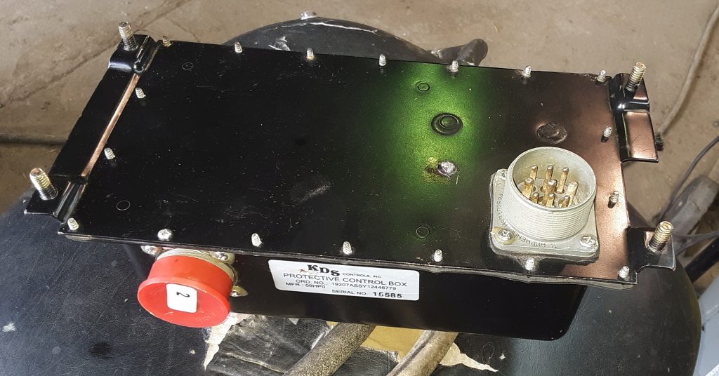
For our M1038, we obtained a mid-series control box, and a corresponding controller. The control box was in unused condition, and its connectors show indications that it has never been connected.
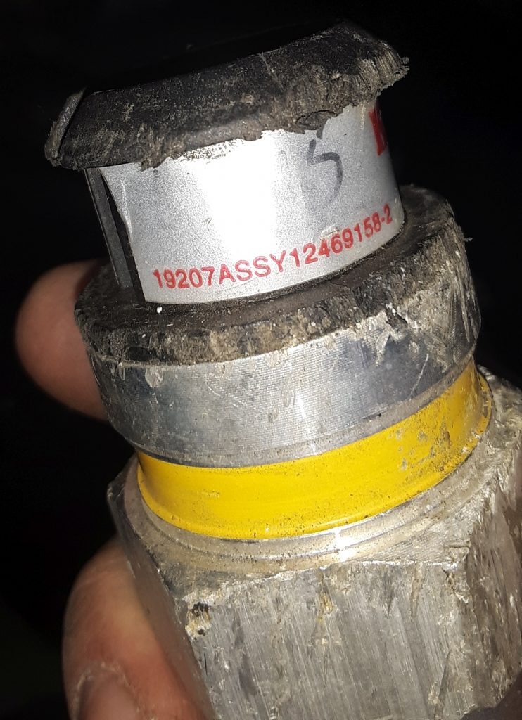
We located a controller that corresponds to the controller, but it had sustained some cosmetic damage.
Information on this controller 19207ASSY12446779 is scant. From what we can determine it was used on the M1113, and is similar to what was used on the M1114. (The M1113 used studs, as on this box, while the M1114 was threaded where the studs are).
It may also be referred to as a “silver label.” To make it clear, these are not EESS boxes. These boxes have been used on trucks up to the m115x, and are the generation between the old yellow/green label ones & the EESS. They are apparently a generation newer than the yellow label control boxes.
We have been cautioned that the operation of this box may make the “wait light” fail to light at higher ambient temperatures, but that is simply because it is not necessary to cycle the glow plugs.
Additionally, we have been cautioned that should a control box fail, there is a possibility that a vehicle fire may result. We will be installing a battery cut-off and will be testing the box before sending the vehicle out the door to reduce the potential for vehicle fire.
We have read good reviews on these boxes and that they are relatively reliable. However, if we note any issues we will reach out to an appropriate vendor for a newer generation control box and controller.
Once the Deep Water Fording (DWF) system has been installed, it is important to test the system for leaks.
Instructions for testing may be found in the “Instructions for Installation of Deep Water Fording Kit” at Section 3-14. The testing consists essentially of:
Block off engine air intake and exhaust, set selector valve to “vent.” (Note, we are unsure as to why blocking off engine air intake and exhaust is necessary — the only connection the DWF vent system has connected to the engine during this test is the vent at the fuel pump). It is imperative, however, to set the selector valve to “vent.”
Disconnect the “42 inch long” hose (CDR valve to selector valve) at the CDR valve.
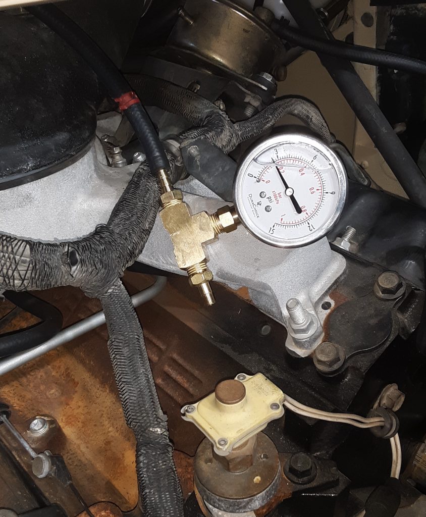
Apply 2.5 to 3.5 p.s.i. into the hose removed from the CDR valve. (Note: there are notes to these instructions found on the internet that have redacted “to selector valve hose” so that it reads apply pressure to the CDR valve. This is incorrect, and doing so would be an attempt to pressurize only the crankcase. Air needs to be applied into the hose leading to the selector valve.)
The system must have at least 1 p.s.i. in the system after 1 minute.
This will check the entire DWF system.
Notes on this test: 1) If there is only a slight leak, testing at 3.5 p.s.i. might pass the 1 minute test, whereas testing at 2.5 p.s.i. would fail the test. 2) It is best to conduct the test in a quiet area so that any leaks can be heard. 3) We recommend use of hand pump only, not a compressor or regulated air source. 4) We suggest making a low pressure leakdown tester as described here. 5) Application of excessive air pressure will likely “blow out,” dislodge or otherwise damage seals in the transmission, transfer case, differentials and gear hubs. Use of other than a hand pump could potentially cause damage in the thousands of dollars to repair.
Our initial testing went well. The tube to the power steering pump had to be removed and blocked because the cap did not seal well enough. After identifying this as a leak point, air was re-applied and was heard leaking into the engine.
As the only point for air to enter the engine would be the vent on the fuel pump, we suspect the fuel pump has a leak into the crankcase. We will first remove the vent line from the fuel pump and test again. If we are able to maintain pressure with that line plugged, we will have to replace the pump.
Our HMMWV failed the 1 minute test, and allows us to diagnose leak points, and potentially catch a fuel into crankcase or fuel into air filter situation.
We will update in a new post as to our further testing. We also want to further examine the venting circuit to ensure that the selector valve should be set to “vent” when testing at the CDR valve.