Photo: Fording Valve

Arrow points to location of fording valve on firewall (located adjacent and behind fuel filter)

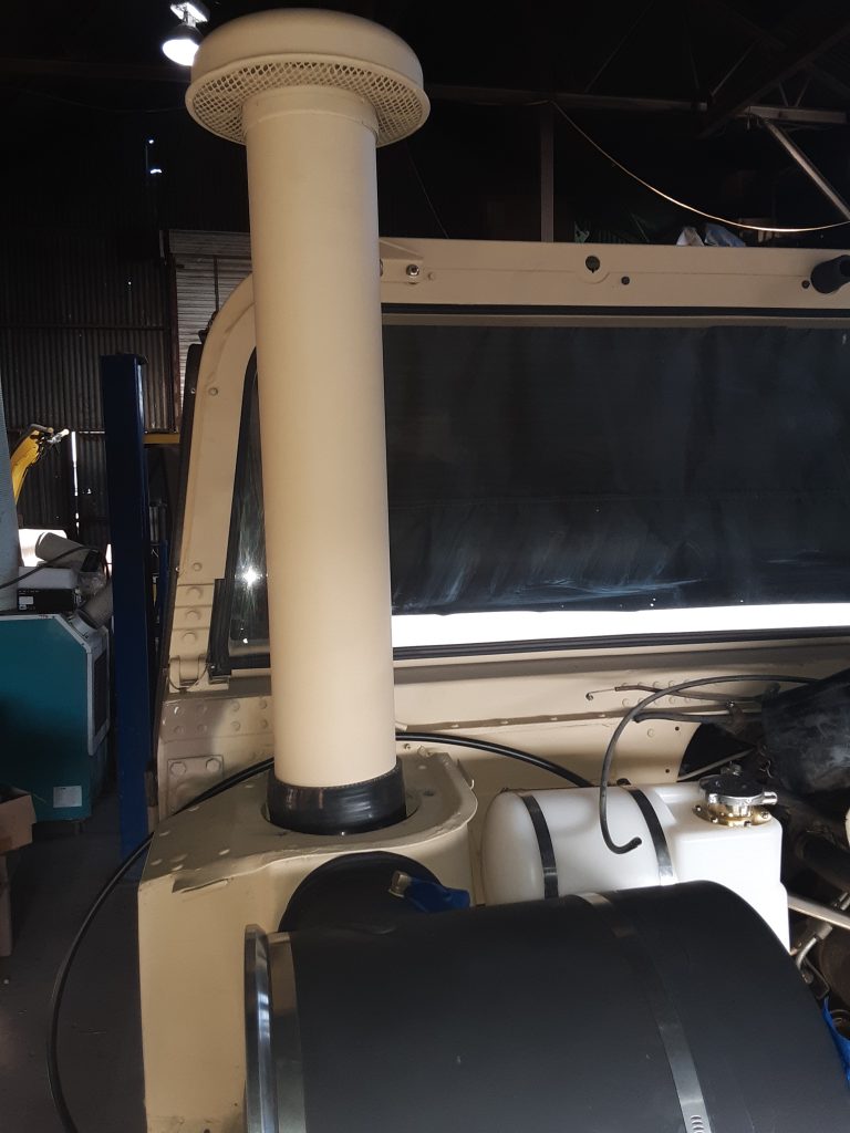
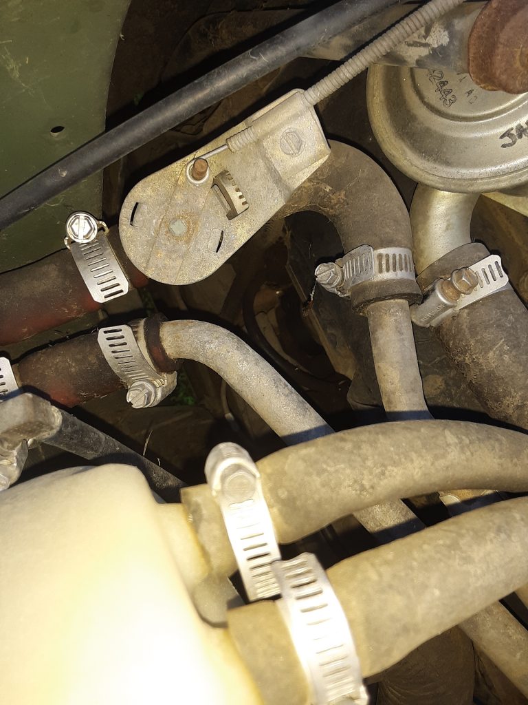
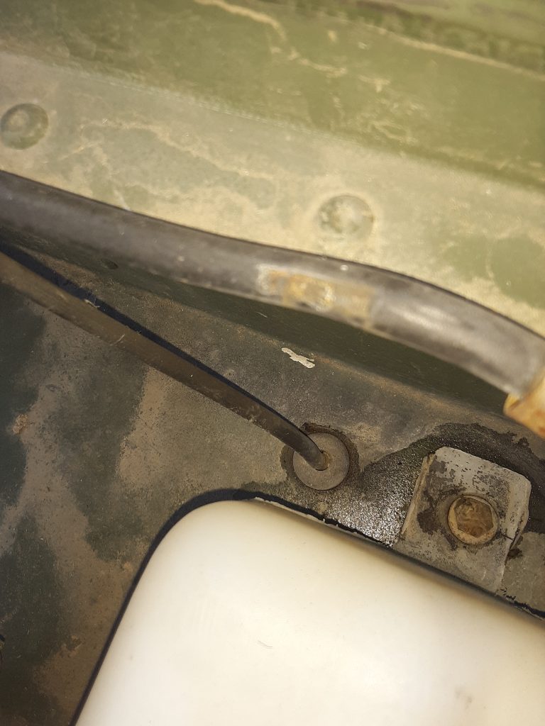
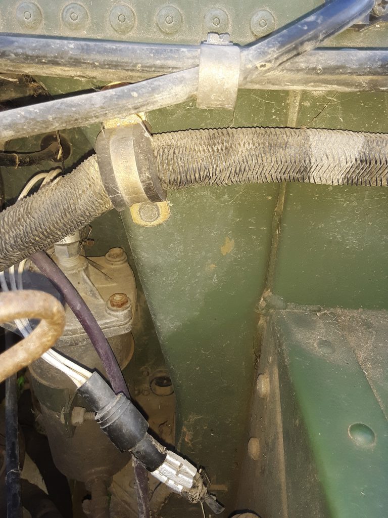
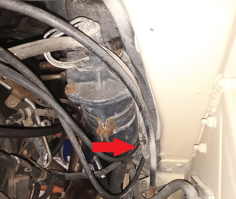
As we are replacing the 30-some year old hose and tubing with new, we need to access the fording valve to remove and replace the hoses. The below picture shows the hoses attached to the fording valve.

Picture of fording valve with arrows pointing at the three hoses attached to fittings.

Both the upper and the middle tubings are called out as P/N CPR104420-1, while the bottom hose is called out as P/N RB1450-1-4IDX1-20D.  As discussed in an earlier post, the CPR104420-1 can be interchanged with 1/4″ air brake tubing, such as Eaton Synflex®. Similarly, we have determined that although not a direct interchange, we could use either 1/4″ silicone hose or 1/4″ SAE J30R9 hose (fuel injection hose). For this application, even though the silicone hose has a much higher temperature rating, we had concern about abrasion on the hose so we substituted the J30R9 hose instead of the silicone. We do however, believe that the silicone hose would be more than acceptable as a substitute under most circumstances.

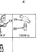
The parts manual shows an exploded view of the hoses and tubing that connect to the fording valve.

Excerpt from Figure 399

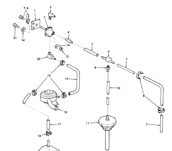
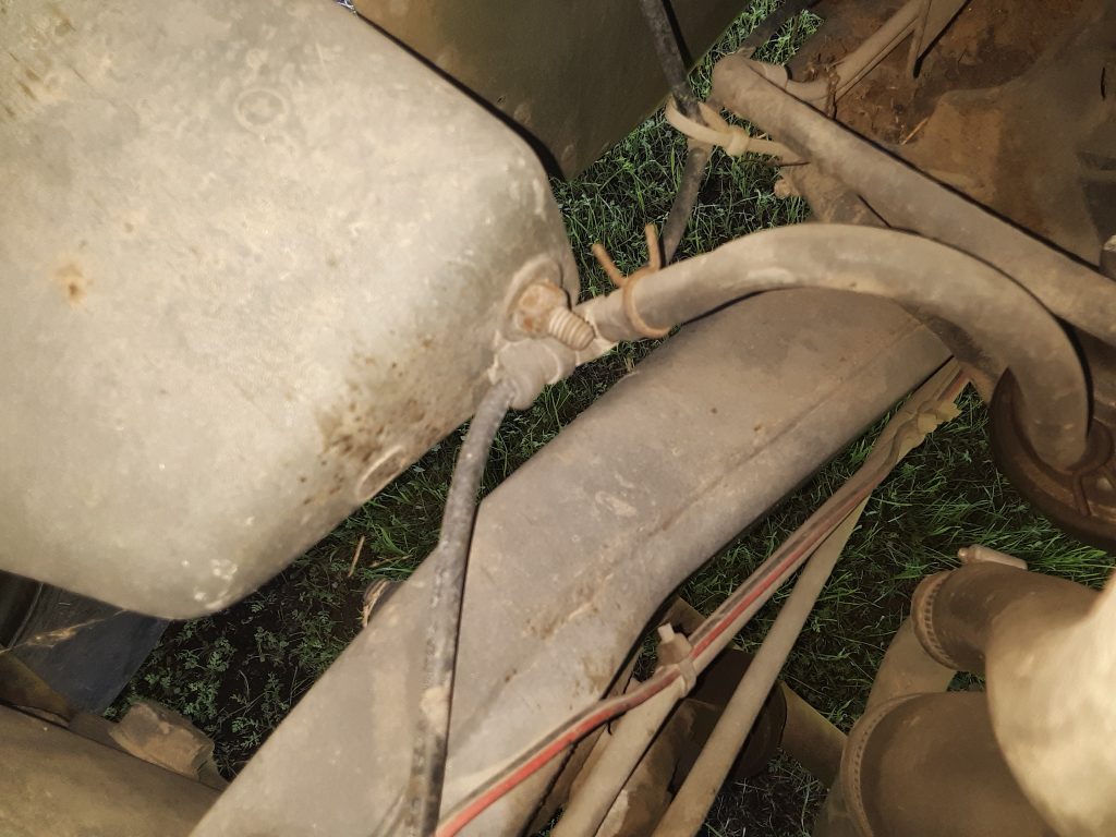
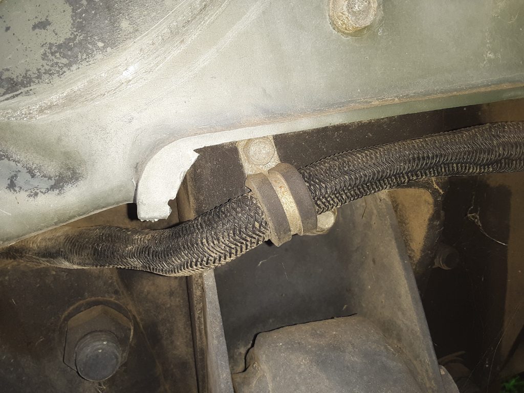
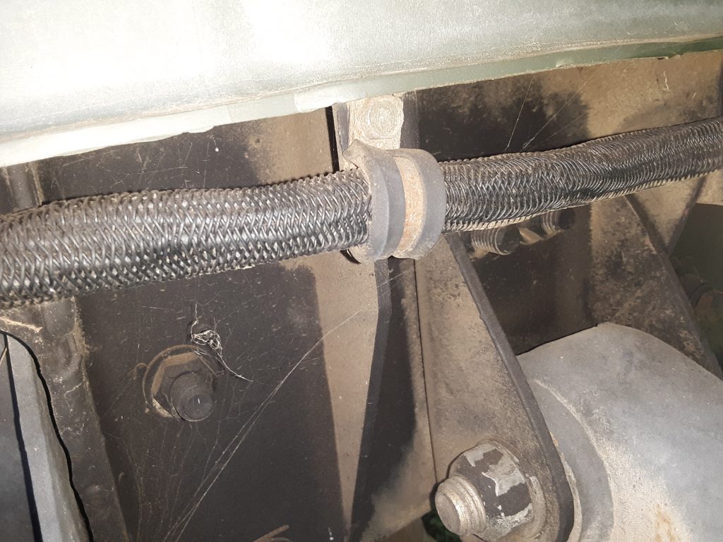
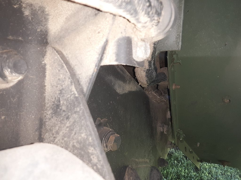
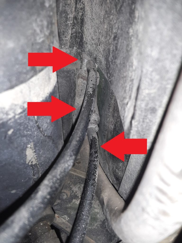
As shown above, the fording valve 4820-01-192-8030 [4820011928030] (Item 2) has three hoses connected to it. The lower hose goes to the lower fitting on the DWF (Deep Water Fording) CDR valve. The middle tubing goes to a line running across the cowling and tees into the vent line from the power steering pump cap. Although this is considered a special cap for DWF applications 2590-01-192-4425 [2590011924425], it is simply a standard power steering cap with a 1/8″ nipple adapter screwed into a hole in the center of the cap.

We have diagrammed the middle hose connection (Item 7) and fording valve top connection (Item 3). to view the diagram, please refer to this updated post.

Installation of Fording Intake Stack

We obtained a complete fording intake stack from Alan Post. By complete, we mean the stack extension 2510-01-198-0333 [2510011980333], the clamps 5340-00-079-7837 [5340000797837], the vent tube 4710-01-209-6746 [4710012096746], and the windshield mount bracket 5340-01-238-9543 [5340012389543] with fasteners.

As you may notice, the rubber extends a little higher than normal at the base of the stack. We had ordered several 4 1/2″ silicone 90°s, to see how they would work. As it turns out, the actual AM General part is slightly less than 90°. Use of the silicone 90° required cutting the end that connects to the air cleaner at a slight “off-angle,” as did the portion that connects to the stack. We have instead ordered the correct fitting to replace this, however use of the silicone 90° would definitely be adequate and completely serviceable.

Update: Interchange: Armstrong Hose RB1450-1-4IDX1-20D

In previous posts, we have indicated that we have substituted RB1450-1-41DX1-20D hose with 1/4″ silicone hose for the vent lines leading from the front hubs to the vent system.

This same hose is indicated for use on vent lines and in the fording kit. We have found that this interchanges to Eaton Weatherhead H10104.

UPDATE (12/29/2018): Apparently AC Delco 32102 (SAE J30R7) is not legal in California. We were denied sale both by Amazon and Ebay vendors.  At this time it appears its illegality is that it has too high of a fuel permeation rate relative to other hose ratings (despite the fact we are using the hose for venting, not fuel). We have ordered SAE J30R9 hose (fuel injection hose) in place of the AC Delco 32102.

J30R9 hose is still quite not identical in specification to the RB1450-1-41DX1-20D hose, as it is is rated to a maximum operating pressure of 100 p.s.i. (compared to the 350 p.s.i. of the Eaton H10104), and a burst pressure of 900 p.s.i. Regardless, for underhood and venting purposes, J30R9 hose will be superior to the J30R7 hose.

The temperature rating of J30R9 is -31°F to 275°F (intermittent to 302°F); which is superior to either the J30R7 or the H10104, although the cold temperature limit has been slightly decreased from -40 F to -37 F.

************************* older information below**************************

We have ordered AC Delco 32102 (the 25′ length of SAE J30R7 1/4″ hose) as a potentially less expensive, but just as serviceable replacement. Our concern is not heat (as silicone has considerably greater working temperature range), but more concern about potential abrasion issues.

This hose is intended for Fuel Line PCV/EEC, and is apparently repackaged Gates hose. Intended for low pressure (50 p.s.i.), this should suffice for venting purposes as well as be able to handle underhood heat. (rated -40 F to 257 F).

It is rated considerably lower than Eaton H10104, which has a pressure rating of 350 p.s.i, but a slightly lower rating of -40 F to 212 F.

Photo: Coolant Return Tube from Heater Core to Water Pump

Picture from M998

UPDATE 1/5/2019: We have identified the NSN of this tube. For our application (an early, low serial number HMMWV), the correct NSN is 4720-01-473-2352 [4720014732352]. The manufacturer number (does not appear to be an AM General number) is RCSK18121.

Later models (SERIAL NUMBER 196901 AND ABOVE) use a different tube, 4710-01-488-6076 [4710014886076], which carries AM General P/N 4710014886076.

Currently using heater hose on this location and trying to locate either NSN or part number for this tubing.

Photo: Front Axle Vent Line to Tee at Fuel Pump

Above images show Figure 141, Item G which is the Tee where the front axle vent connects to the fuel pump and the vent line leading from the rear axle, transmission and transfer case.

This Tee consists of TEE, PIPE TO HOSE 4730-01-192-8086 [4730011928086] and a pipe to hose adapter, 4730-01-004-8346 [4730010048346]. Hose “3” in the picture goes to the upper connection on the fuel pump where fuel will leak into the venting system if the diaphragm fails.

As shown in the picture below, the tee is mounted by clamp 5340-00-067-3868 [5340000673868] (MS21333-109) which is a 1/4″ I.D. clamp with a 1/4″ attachment hole. It mounts to the RH side splash guard 2540-01-174-7696 [2540011747696]. (We believe this clamp has been used as a substitute for the spring tension clamp View “H” 5340-01-187-0892 [5340011870892])

Picture from M998

Photo: Filter Status Monitor Hose to Body

Picture from M998

Above shows the entry location and grommet for the hose from the air filter to the filter status gauge.

UPDATE: The Project M1038 does not have a hole in this location. We are attempting to determine whether a filter status monitor was available in the early serial numbers, and if so, if the hosing was routed differently. Before we drill a hole, we will determine whether it would have been upgraded had it remained in service.

Photo: Body Harness to Frame (Front)

Picture from M998 (front clamp)
Picture from M998 (intermediate clamp)
Picture from M998 (rear clamp)

Views of Figure 84, View I (there are three according to parts manual), body harness to front frame (leading to hood wiring). Clamps are 5340-00-088-1254 [5340000881254] (MS21333-104). These clamps are 5/8″ inside diameter, 1/2″ wide band, with a 1/4″ mounting hole.