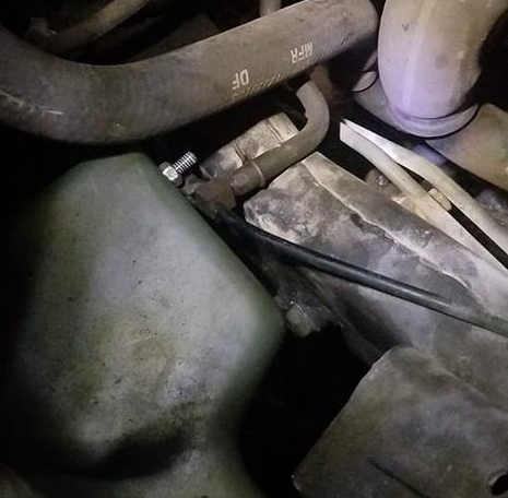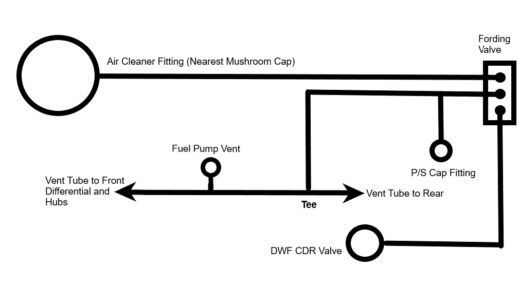
In the above diagram, a section of RB1450-1-4IDX1-20D hose (or suitable substitute such as 1/4″ SAE J30R9) goes from the bottom fitting on the fording valve to the DWF CDR valve. A section of CPR104420-1 (or suitable substitute such as Synflex® 1/4″ air brake tubing) runs from the middle port of the fording valve to a tee (where it connects to the power steering cap) and to another tee located in the vent line running along the top of the RH frame rail. The picture below shows where this tee is located
Note above picture is of a M998 without DWF. Lacking DWF capability, this line vents directly to the air cleaner at the fitting nearest the mushroom cap. When a DWF kit is installed, this line from the air cleaner is rerouted to the upper fitting of the fording valve, and this tee becomes connected (through a new line which includes a new tee to the power steering cap) to the middle port of the fording valve.
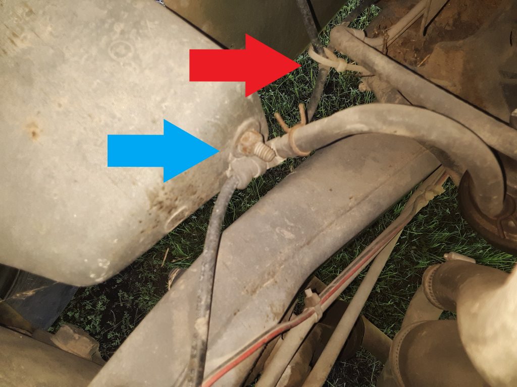
Blue arrow indicates the “tee” where the vent from the fuel pump connects to the vent line.
After completing this post, we located a copy of instructions for installing a DWF kit at: http://www.hummerknowledgebase.com/driving/dwf.html These instructions are less than clear. However, they may provide additional information regarding Deep Water Fording equipment.
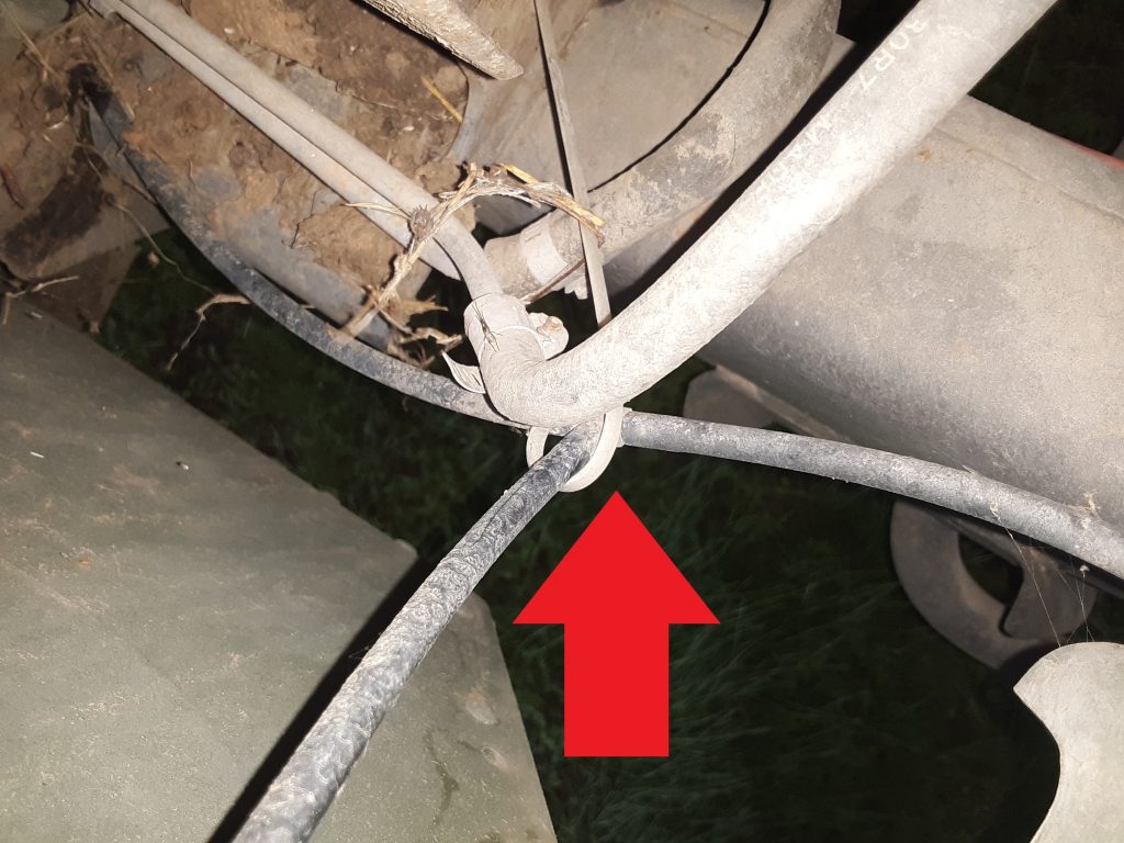
Update 1/14/2018: As seen in the picture below, the cushion clamp is placed to the rear of the tee (which corresponds with the parts manual exploded view). As of this time, we do not believe it to be crucial whether the cushion clamp is forward or behind the fuel pump vent tee. What it perhaps more crucial is the existence of the cushion clamp and that it is properly tightened.