After installation of the 10,000 lb. winch, we went back to ensure all proper warning and instructional decals were applied in their proper places.
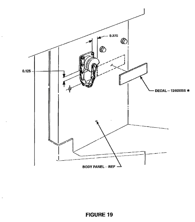
The instruction manual calls out 12469066 [ 7690-01-474-5928 / 7690014745928; Mile Marker 983-0021] being applied near the winch controller connector. Unfortunately, we did not receive that decal in our installation kit. Additionally, we were unable to locate an image of the decal, or even what it warned of.
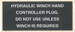
Ultimately we were able to purchase the decal from Kascar, LLC who had several in stock. We purchased additional decals in the event we need them in the future, or were required to reproduce or make a similar decal for future installs. Below is a scan of that sticker for reference to the text included on it.
12469066 / MM 983-0021 / 7690-01-474-5928 / 7690014745928
The main task was transferring all of the hardware from the other fuel tank to the new fuel tank. We used Gasqacinch on the rubber gasket for an additional level of leak protection, and because it permits easy removal of the gasket in the future.
We learned that it is better to install the vent fittings on the tank prior to installation. Additionally, it would have also been beneficial to install the front heat shield prior to installation. However, both of these tasks can be completed with the tank mounted.
Rear of 5582606 fuel tank showing relieved area to clear parking brake.
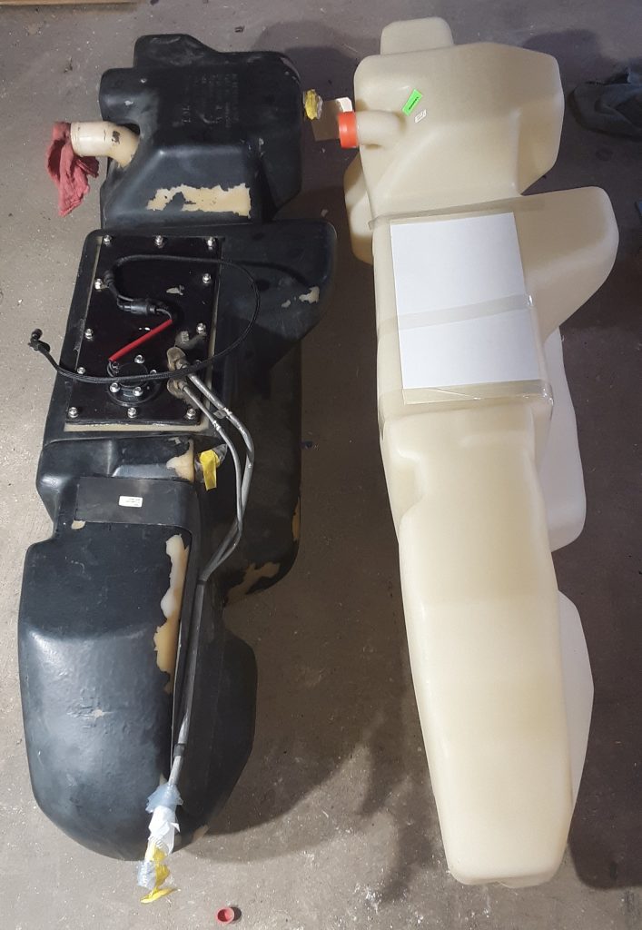
Side-by-side of fuel tanks. (left) 2910-01-447-3911 [2910014473911] and (right) 5582606
After receiving and unboxing our newly arrived 5582606 fuel tank, we decided to do a side-by-side comparison of them. As visible from the picture above, the later model tank is distinctly larger.
Visible on the rear of the tank is the cut-out allowed for the drive line parking brake.
Also of note is that the tank skidplate does not fit the older-style tank. Although we could have cut and used a brake to rebend it, we will store it for a future project. Additionally, it is clear that removal of the driveline would not be required to install or drop the older-style tank because of its reduced size.
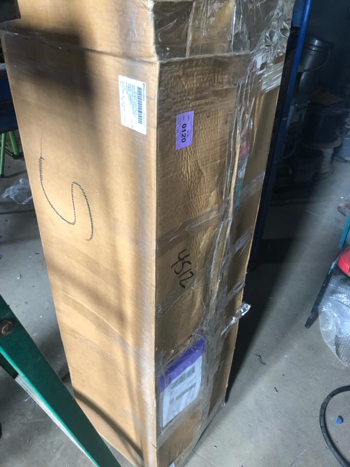
As explained in an earlier post, we unknowingly attempted to install a later model fuel tank into an early model HMMWV. And despite difficulty in locating the correct tank, we were able to. It arrived today, and we intend to install it in the next few days.
Boxed fuel tank 5582606 for early serial number HMMWVs with separate parking brake
As we install this tank, we will attempt to document and post any differences between this main fuel tank and the early tank.
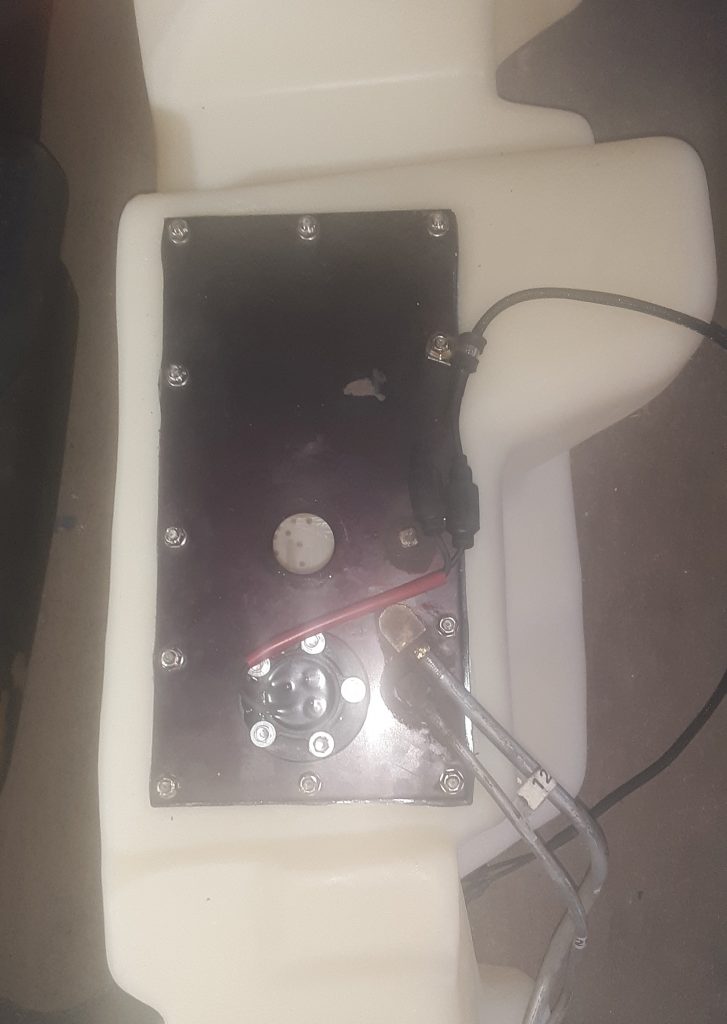
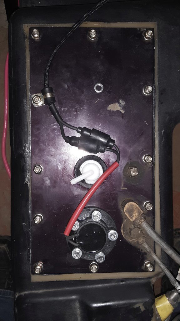
We had purchased a fuel tank for our M1038, as well as the missing straps, fuel level sender and other pertinent parts, and were ready for installation.
Top view of fuel tank ready to be installed
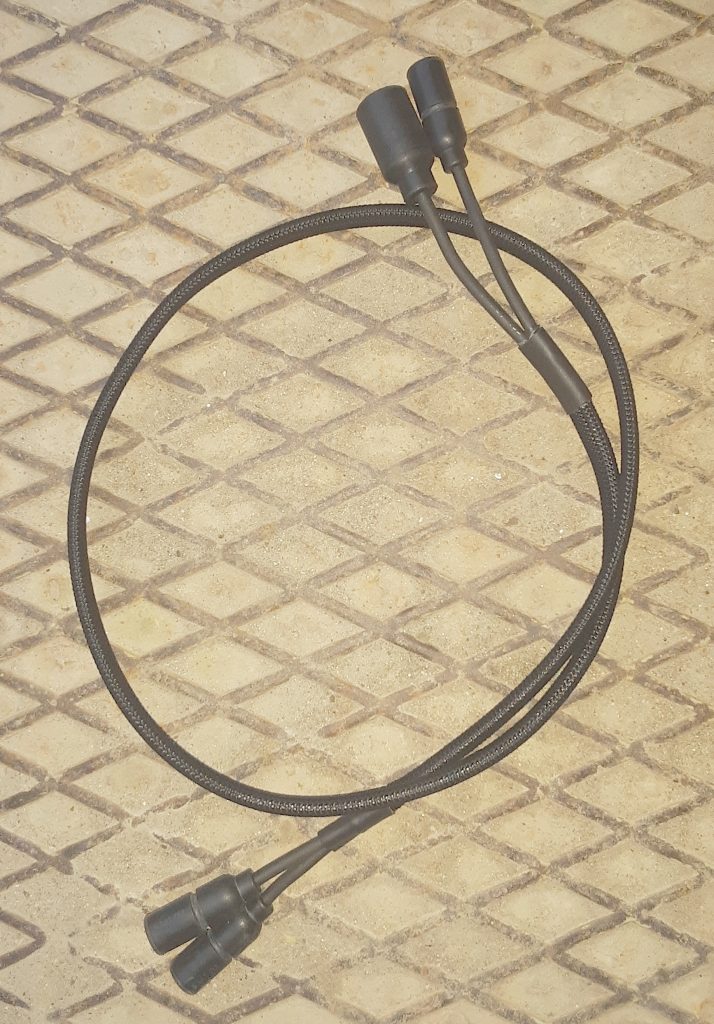
We were unaware, however, that the jumper between the fuel tank and the wiring harness was missing. So, using the correct Prestolite wire, wiring ends, and PET loom, we fabricated a replacement jumper. (Ensuring that it was made to military specifications).
UPDATE 3/ 24/2019: We fabricated the jumper at a 36″ length. As it turned out, the length could have easily also be made at 18″-24″ length. As it turned out, we cable-tied the excess to the fuel tank vent tube near the crossmember where the jumper connects to the harness. We suspect that should we have to remove the tank in the future, the extra length will prove “slack” to permit us to lower the tank without having to disconnect the jumper from the harness.
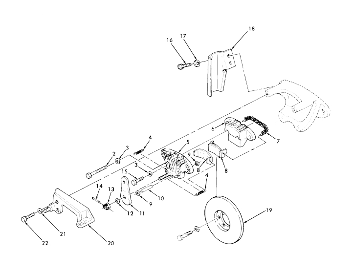
We were ready to install. Or so we thought. Even after removing the driveline, we found that we could not physically fit the tank into the area, as it hit the emergency brake caliper, rotor, and bracket.
We were simply unaware there was more than one main fuel tank. Our tank 2910-01-447-3911 [2910014473911] carries part number 12460105, and is easily located. As it turns out, we should have verified application through the UOC (Usable On Code) found in the parts TM in the far right side under description.
The UOC for a M998 is H13, whereas the UOC for a M1038 is H14. For practical purposes (other than differences between having a winch or not) either code would be accurate.
As it turned out, the NSN for the tank we had did not have the correct UOC, and we found the tank we required was part number 5582606, with no NSN provided for a part number. We simply had the wrong tank.
Through further research, we were able to identify a serial number split from 1 thru 44824, which uses the brake mounted against the rear differential on the driveshaft side. 2530-01-174-7441 [2530011747441].
We are well aware of operator complaints regarding this parking brake, but have found to often that operators attempt to adjust the brake from the brake handle adjustment (which is meant only to adjust for slack in the cable), and not properly adjust the brake from the caliper adjustment. We purposely chose to maintain this brake system because of our unit’s 4 digit serial number for historical purposes.
However, as noted above, we were completely unaware that maintaining this brake would require a fuel tank of limited availability.
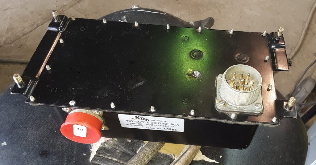
For our M1038, we obtained a mid-series control box, and a corresponding controller. The control box was in unused condition, and its connectors show indications that it has never been connected.
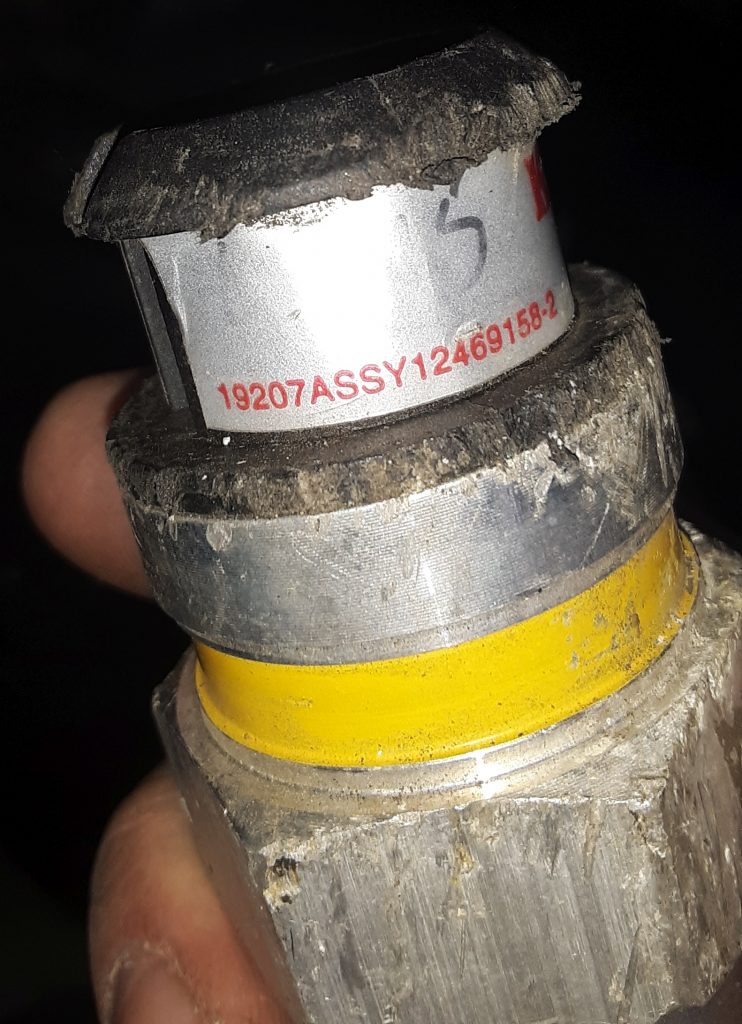
We located a controller that corresponds to the controller, but it had sustained some cosmetic damage.
Information on this controller 19207ASSY12446779 is scant. From what we can determine it was used on the M1113, and is similar to what was used on the M1114. (The M1113 used studs, as on this box, while the M1114 was threaded where the studs are).
It may also be referred to as a “silver label.” To make it clear, these are not EESS boxes. These boxes have been used on trucks up to the m115x, and are the generation between the old yellow/green label ones & the EESS. They are apparently a generation newer than the yellow label control boxes.
We have been cautioned that the operation of this box may make the “wait light” fail to light at higher ambient temperatures, but that is simply because it is not necessary to cycle the glow plugs.
Additionally, we have been cautioned that should a control box fail, there is a possibility that a vehicle fire may result. We will be installing a battery cut-off and will be testing the box before sending the vehicle out the door to reduce the potential for vehicle fire.
We have read good reviews on these boxes and that they are relatively reliable. However, if we note any issues we will reach out to an appropriate vendor for a newer generation control box and controller.
As discussed in a previous post, We removed the shunt and coated the entire interior of the battery box with the rubberized undercoating to protect the aluminum against corrosion from battery acid.
It seems that most people fail to understand the difficulty of
repairing or the time and expense to repair damaged transmission cooling
lines. Both the lines in our M1038 and from our new powerplant were
damaged, and unusable.
We could have just substituted hose for the lines. However, tubing is
far sturdier, and rated for higher pressures. Consequently, tubing is
less likely to fail than a long length of hose. Arguably, there is some
cooling effect to be accomplished just from the +/- 20 feet of line.
We determined that it would be virtually impossible to install
factory cooling lines without removing the cooling stack and possibly
even the powertrain. As a result, we used 3/8″ brake tubing and made our
own.
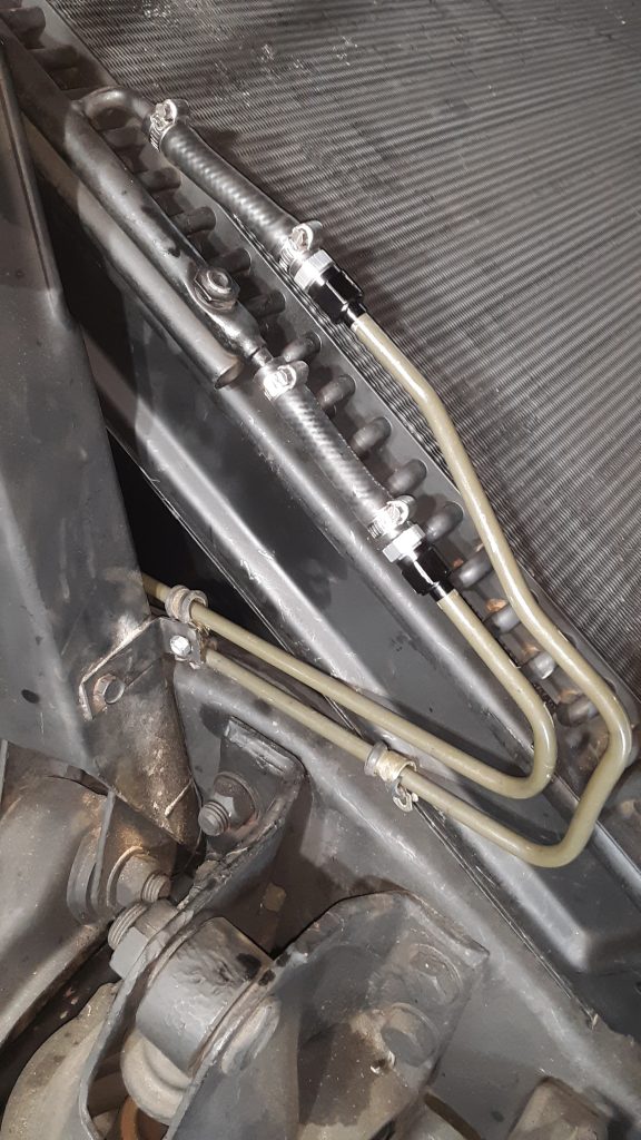
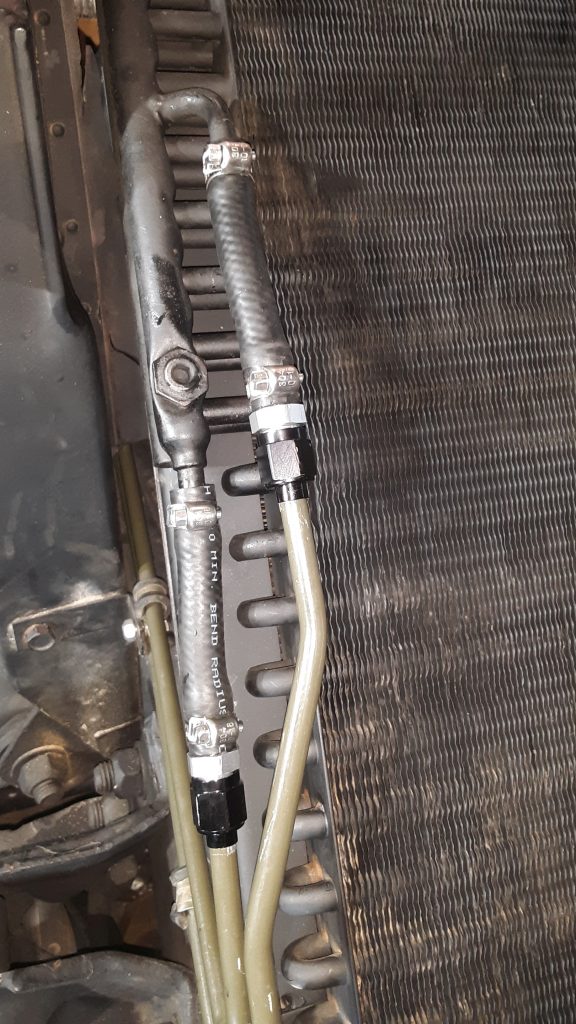
Custom fabricated transmission cooling lines to cooler (new cushion clamps are on order)
We fabricated our cooling lines in two pieces (each line) that joins at the frame near the idler arm. This allowed us to have the complex bends on the front section, and allows for it to be somewhat easily installed. We do not have a 3/8″ beading tool — If we did, we would simply have beaded the ends. However, using a Ridgid 41162 377 flaring tool (which provides the proper 37 degree angle for AN fittings) and used Russell -6 AN tube sleeves and nuts to connect an AN to 3/8″ hose barb. This ensures a leak-free connection.
Although the transmission pressure through the cooler only reaches a
maximum of 30 p.s.i., we were still concerned about preventing leaks
between the hose and the tubing without having a bead.
Although the AN connectors are not cheap, we already owned the Ridgid
flaring tool, and the cost of the fittings was considerably less than a
beading tool.
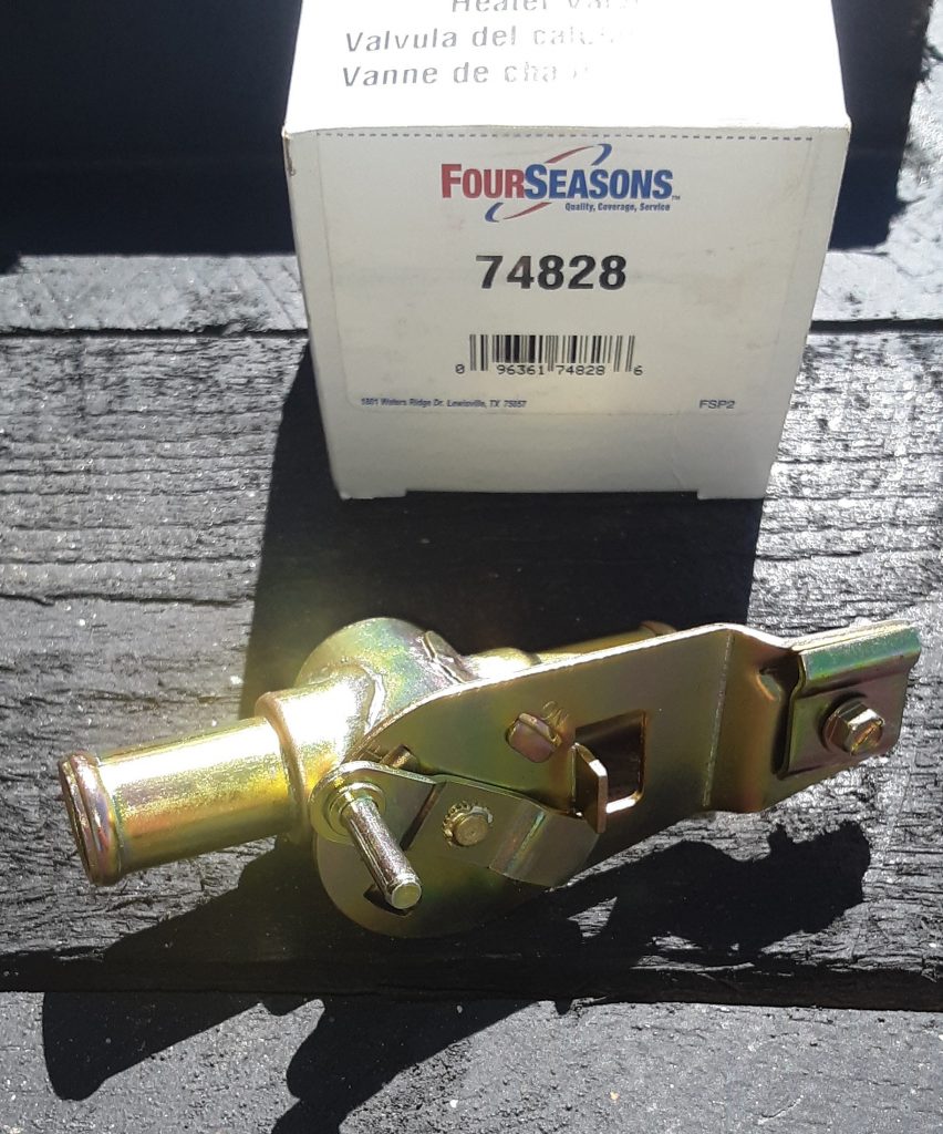
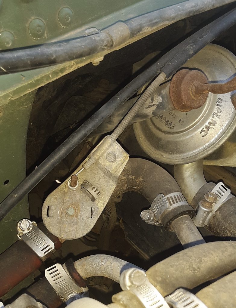
The Heater Control Valve 4820-01-189-2107 [4820011892107] (AMG 12339966) was missing from our vehicle. We researched the different aftermarket valves available and were able to locate a replacement: Four Seasons P/N 74828.
This appears dimensionally identical to one in an M998:
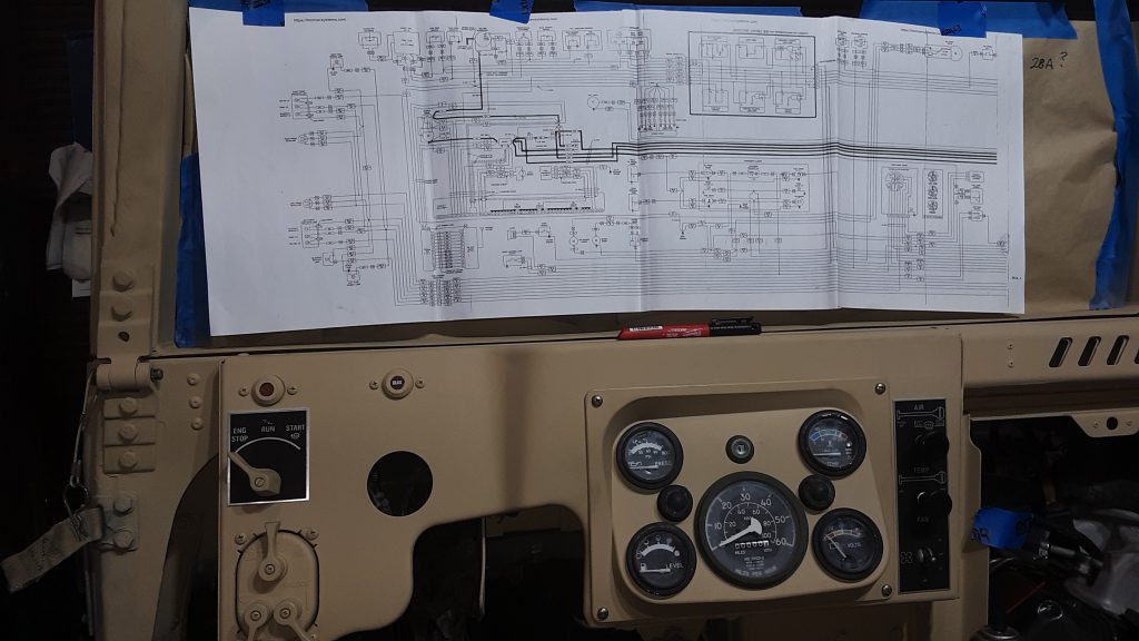
As this HMMWV did not have a dash or gauges installed, we had to identify each wire by number from the wiring diagram. We put tape on each wire and marked where it belonged. We found it simplest to tape the wiring diagram to the windshield to assist in wire location identification.
Through this process, we located where a 3 wire bundle had been cut off. Through the process of elimination, it appears that these wires are for the headlight dimmer switch. We will have to fabricate a new section which will involve soldering and splicing to the existing harness using waterproof marine heatshrink tube..