Leakdown Testing the Deep Water Fording System

Once the Deep Water Fording (DWF) system has been installed, it is important to test the system for leaks.

Instructions for testing may be found in the “Instructions for Installation of Deep Water Fording Kit” at Section 3-14. The testing consists essentially of:

  • Block off engine air intake and exhaust, set selector valve to “vent.” (Note, we are unsure as to why blocking off engine air intake and exhaust is necessary — the only connection the DWF vent system has connected to the engine during this test is the vent at the fuel pump). It is imperative, however, to set the selector valve to “vent.”
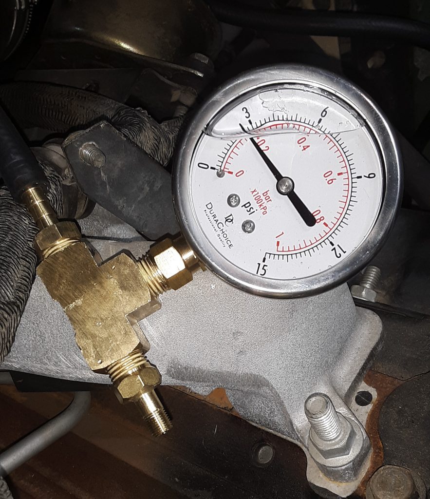
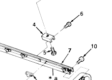
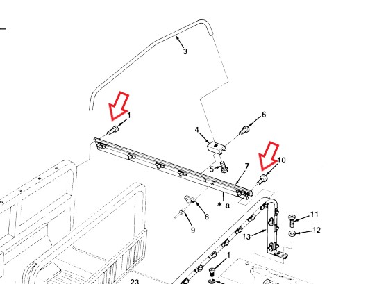
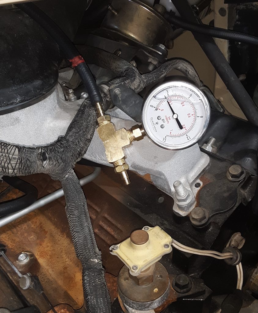
  • Disconnect the “42 inch long” hose (CDR valve to selector valve) at the CDR valve.
  • Apply 2.5 to 3.5 p.s.i. into the hose removed from the CDR valve. (Note: there are notes to these instructions found on the internet that have redacted “to selector valve hose” so that it reads apply pressure to the CDR valve. This is incorrect, and doing so would be an attempt to pressurize only the crankcase. Air needs to be applied into the hose leading to the selector valve.)
  • The system must have at least 1 p.s.i. in the system after 1 minute.
  • This will check the entire DWF system.

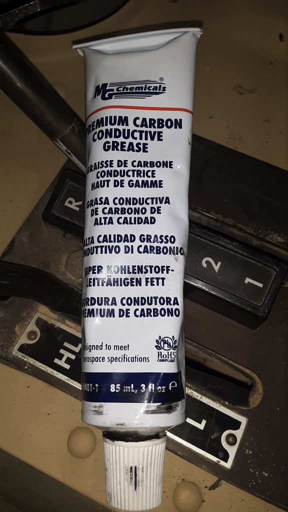
Notes on this test: 1) If there is only a slight leak, testing at 3.5 p.s.i. might pass the 1 minute test, whereas testing at 2.5 p.s.i. would fail the test. 2) It is best to conduct the test in a quiet area so that any leaks can be heard. 3) We recommend use of hand pump only, not a compressor or regulated air source. 4) We suggest making a low pressure leakdown tester as described here. 5) Application of excessive air pressure will likely “blow out,” dislodge or otherwise damage seals in the transmission, transfer case, differentials and gear hubs. Use of other than a hand pump could potentially cause damage in the thousands of dollars to repair.

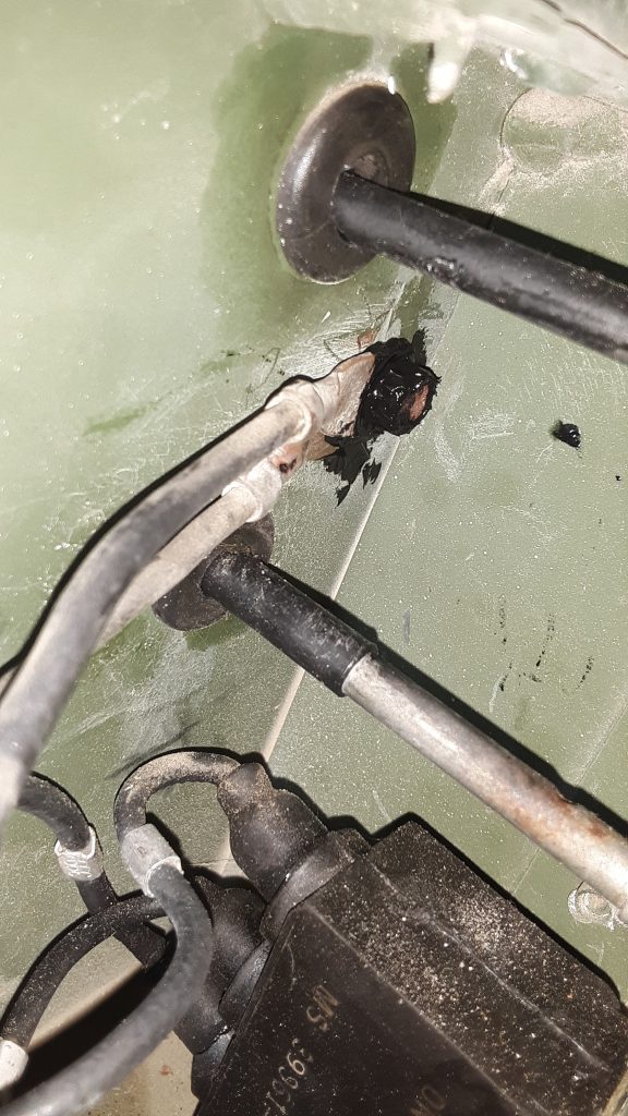
Our initial testing went well. The tube to the power steering pump had to be removed and blocked because the cap did not seal well enough. After identifying this as a leak point, air was re-applied and was heard leaking into the engine.

As the only point for air to enter the engine would be the vent on the fuel pump, we suspect the fuel pump has a leak into the crankcase. We will first remove the vent line from the fuel pump and test again. If we are able to maintain pressure with that line plugged, we will have to replace the pump.

Our HMMWV failed the 1 minute test, and allows us to diagnose leak points, and potentially catch a fuel into crankcase or fuel into air filter situation.

We will update in a new post as to our further testing. We also want to further examine the venting circuit to ensure that the selector valve should be set to “vent” when testing at the CDR valve.

Special Tools – Fording System Leakdown Tester

In order to confirm that all Deep Water Fording (DWF) vent lines, transmission seals, differential seals, etc are sealed, a leak down test is required.

Pictured above is a leakdown tester we assembled. We used a 1/4″ NPT brass tee, a 1/4″ NPT x 1/4″ hose barb, a 1/4″ NPT x Schrader valve, and a low pressure gauge (0-15 p.s.i.).

You may note that we used a glycerin-filled gauge. A glycerin-filled gauge adds a level of dampening in an application where shock-loading frequently occurs. It is unnecessary for this application, however the cost was only slightly higher than a non-filled gauge. Of note, filled gauges often have a small brass plug mounted in rubber to allow you to zero the gauge out if atmospheric pressure has raised it from zero.

WARNING AND CAUTION: We highly recommend using a hand pump, such as a bicycle tire pump. Should you put excessive pressure into the system while testing, it is highly likely that you will “blow out” seals, and potentially damage seals in the engine, transmission, gear hubs, and differentials. It takes a very little amount of air to reach 2 to 3 p.s.i., and even use of regulated air may provide a “burp” of air at a pressure sufficient to dislodge or destroy seals.

Wiring: Restoring/Preserving Cannon (Amphenol) Plugs

Cannon plug missing anodizing and with corrosion

Most of the cannon plugs (also referred to as Amphenol plugs) had most of their protective anodizing missing. The internal contacts were good and clean. Rather than spend an incredible amount of time and expense of moving the connectors into new fittings, we opted to preserve the exterior of the plug. We use a two-step process of etching primer followed by a lustreless olive drab marketed by Rapco Parts.


The first step is to use a small stainless steel to remove all corrosion from the outside of the plug. The second step is to apply the etching primer and let it fully dry.

Although the etching primer produces a color that is acceptably close to the original anodizing, primer does not make a good final coat.

The final coat of lusterless olive drab (FS 34086) is very close to the original color of the plug, and having a paint coating on the aluminum housing will extend the service life of the connector and assist in preserving the integrity of the electrical connections.

As a note, we applied the silicone grease to the threads and connections to prevent corrosion of the threads and to provide a slight amount of additional waterproofing to the contacts in the event the cannon plug seal fails.

Wiring: Dash Ground

Use of carbon grease on dash ground

The HMMWV has a reputation for grounding issues. Poor grounding can cause faulty or unreliable gauge readings, and can also cause failure of components including the control box.

We removed and cleaned all connections, and liberally applied carbon grease to all contacts to ensure the best possible connection. After this photo was taken, excess carbon grease was wiped off. This compound is highly conductive, and it is unwise to not clean up after a sloppy application.

MG Chemicals’ Premium Carbon Conductive Grease

Wiring: Silicone Lubricant / Waterproofing

Military Surplus Silicone Waterproofing

Anytime wiring with rubber boots are involved, it is always best to use a silicone lubricant. This assists in assembling the components, protects the rubber, and provides a further degree of waterproofing.

We have almost two cases of military surplus J941-C-5000 (also known as NRL S-75-G), which we acquired in the 1980’s. Since then, we have liberally used the silicone, and despite its age (Manufactured in 1954), it continues to be usable. Not bad for a 65 year old product!

We were unable to find further information of any kind on this product, however we have 30+ years using this material and have had superb results.

UPDATE: NRL S-75-G Interim was developed in World War II as a waterproofing lubricant to prevent machine gun failure caused by moisture freezing in solenoids at high altitudes (-20 F temperatures). (these failures are indicated as affecting the Cal .50 M3 and the 20 mm M24A1 Gun).

“The material is an open chain methyl silicone having a viscosity of 20 cSt at 77°F, and 300 cSt at -65°F, and a pour point of -75°F. Dodecane phosphoric acid (0.1 percent by weight) was added for lubrication. This material was labeled NRL S-75-G Interim.” Per: AMCP 706-26 at page 8-2 (Engineering Design Handbook, Guns Series, Automatic Weapons, Headquarters, U.S. Army Materiel Command, February 1970 [Document unclassified, but not marked as publicly released]).

Interchange: Bow to Soft Top Rails

The screws attaching the bows to the side rails (Fig. 321, Item 6) calls out as 5305-00-059-3659 [5305000593659] with a general fastener number of MS51958-63 is essentially a 10-32 x 1/2″ pan head screw. Although we feel a standard 10-32 screw would be sufficient, we were able to source a number of the actual fasteners designated MS51958-63 at around the base price of the fastener from major vendors.

Although it is highly likely that a standard 10-32 screw would suffice in this application, we feel that use of the correct military fastener may give a slight performance advantage in both strength and corrosion resistance.

Of note, however, the fasteners we acquired indicate they are stainless, which is generally of a strength equivalent to a Grade 5 bolt. (of course, this depends on the type of stainless). We believe the vendor has mistaken plated fasteners as stainless. The packaging of the fasteners state they are MS51958-63. We have not reviewed the specifications of this fastener, but are of the opinion that even if stainless, they should suffice for holding the bows to the side rails.

Interchange: Soft Top Side Rail Screws (NAS1635-3LE12)

The screws at the front, middle, and rear of each rail are called out by different part numbers in the TM. The front screw (#1) 5305-01-210-6249 [5305012106249] with a manufacturer P/N of PL25D02P12 was not locatable.

The screw at the rear of the rail (#10) 5305-01-117-3396 [5305011173396] was similarly unlocatable, however we were able to locate this screw by its manufacturer P/N of NAS1635-3LE12. This is essentially a #10-32 x 3/4 screw. However, this has pre-applied locking compound. Additionally, we surmise this screw probably has a higher tensile strength than a standard 10-32 screw as it is an aircraft fastener.

As for the PL25D02P12 fastener called out for the front connection, at least one vendor (Kascar/real4wd.com) lists the NAS1635-3LE12 as an interchange. (at time of post, searching for the PL25D02P12 fastener comes up as NAS1635-3LE12) See: https://real4wd.com/store/catalog/search.aspx?keywords=PL25D02P12

In other words, we are comfortable that since both fasteners specifications are as a self-locking 10-32 x 3/4″, that use of the NAS1635-3LE12 is proper. There are apparently 50 in a box, and we have ordered 4 boxes to keep in stock.

Wiring – Preparation for Dash Wiring

Rapco “686” Tan applied to dash and vent areas. Note: Paint is still wet, when dry it is completely flat.

Prior to assembling the gauge cluster, lighting switches, filter minder and other connections, we prepped the existing CARC to accept paint. Special attention was paid to masking the window rubber, as paint can rapidly degrade it. This was painted in Rapco “686” Tan (which corresponds with FS 33446).

By pre-painting the dash and vent areas, it ensures an even color when these areas are masked off for complete vehicle paint.

Renovating Shifter Controls: Transmission Shifter Bushing

As our shifter was frozen solid, it required use of a hydraulic press, hammer, and punch to dissasemble the shifting mechanisms. In the process, we ended up destroying both the shaft and the bushing.

This bushing 3120-01-191-3232 [3120011913232] (indicated by red arrow) is made of thin nylon. Although after looking at it, we could have replaced it with an oilite or brass bushing, that would require machining of the shifting bracket. We then attempted to source the bushing using the NSN with no luck. However, we were able to located the part (currently available for order) from the manufacturer using the part number 10L18F. Applied Industrial Technologies carries this part available at https://www.applied.com/c-brands/c-thomson-industries/10l18f/Thomson-Nyliner-Bearing/p/101610126.

Renovating Shifter Controls: Reverse Light Switch

Early shifter control for basic and A1 versions

The transmission shifter in our M1038 was frozen, in that the release button could not be depressed to release the shifter. Additionally, the lever 2520-01-189-1064 [2520011891064] (Fig. 99, Item 16) was broken at the connection point. After removing the entire assembly, we noticed that this was an atypical shifter in that it had not only the safety switch 2920-01-249-3492 [2920012493492](Fig. 99, Item 20), but also a reverse light switch (not shown in diagram).

Shifter showing neutral safety switch and reverse light switch. Reverse switch is the right arrow.

It is our current understanding that the reverse light switch was used only on Marine HMMWVs, but that it is also desirable for on-road civilian use in states that require a functioning reverse light. The lead from one of the wires was 467 (whereas the neutral safety is 14). Of note, the hole for the reverse switch appears to exist in all of the housing assemblies (Fig. 99, Item 10). (See diagram). Of further note, the switch appears to be the same as the neutral safety other than there is a bushing installed to allow the smaller switch to be installed in a larger hole

Arrow showing reverse light switch. Note bushing surrounding switch.

From this, it appears that a reverse light switch can be installed in any of the earlier shifters. Once we identify the threaded bushing dimensions, we will post it. It seems relatively difficult to source the reverse light switch as opposed to the neutral safety switch.

Neutral Safety Wire #4, Reverse Light Wire 467