Control Box & Controller

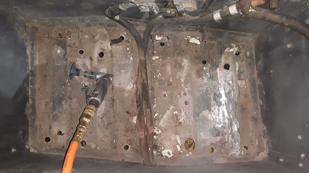
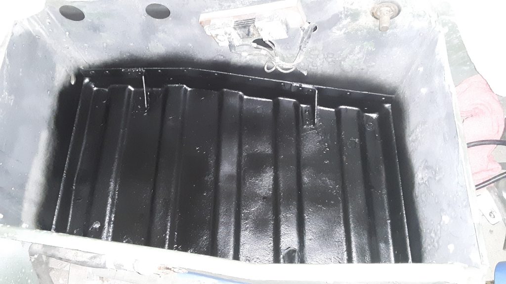
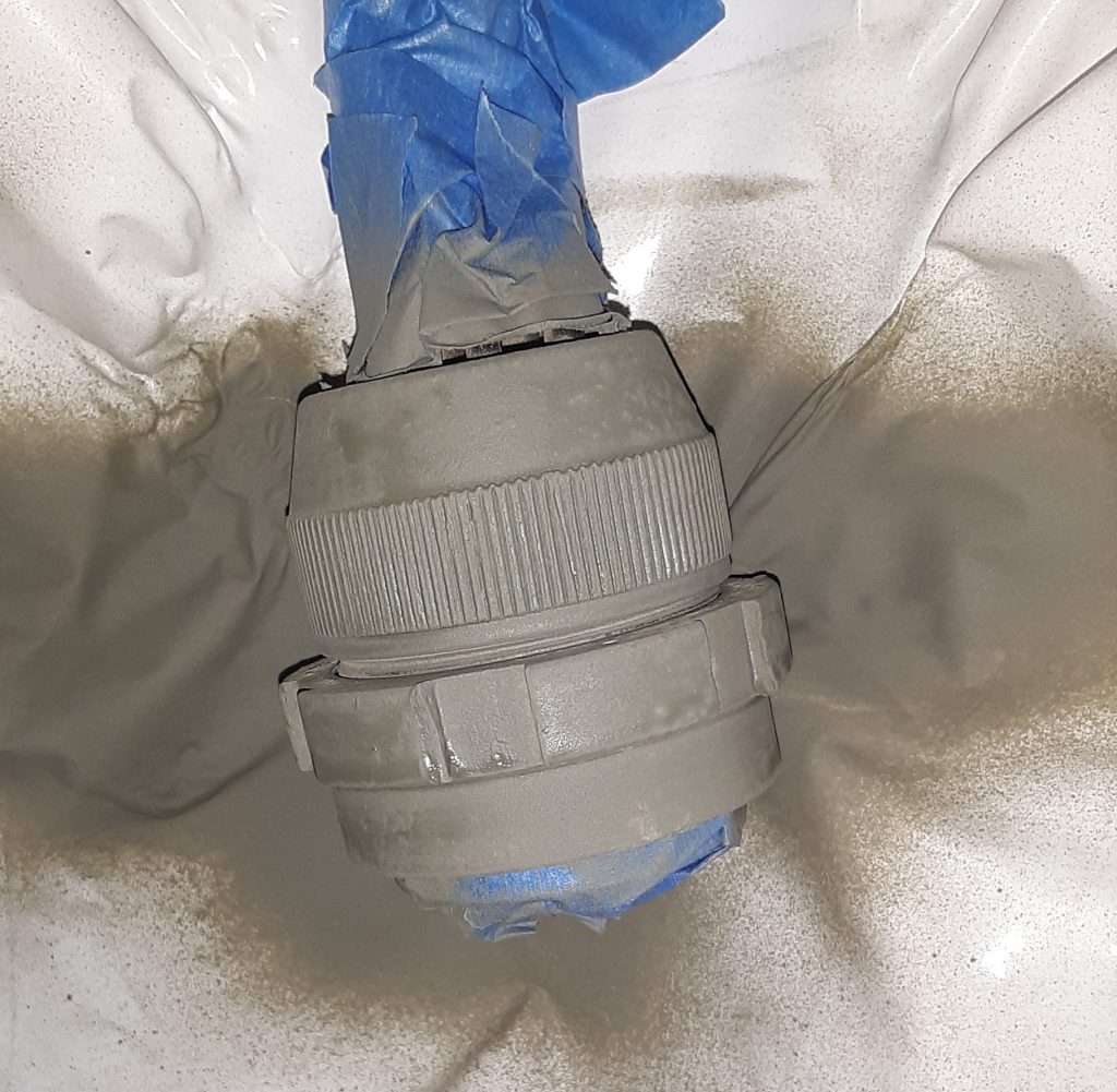
For our M1038, we obtained a mid-series control box, and a corresponding controller. The control box was in unused condition, and its connectors show indications that it has never been connected.

We located a controller that corresponds to the controller, but it had sustained some cosmetic damage.

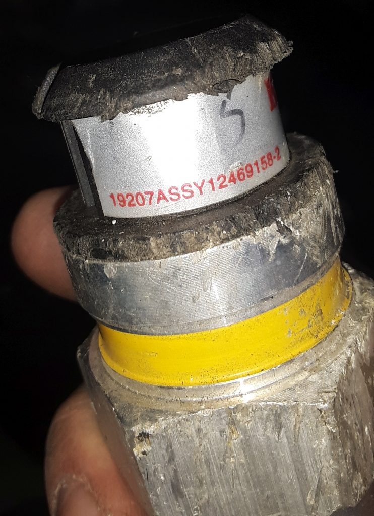
Information on this controller 19207ASSY12446779 is scant. From what we can determine it was used on the M1113, and is similar to what was used on the M1114. (The M1113 used studs, as on this box, while the M1114 was threaded where the studs are).

It may also be referred to as a “silver label.” To make it clear, these are not EESS boxes. These boxes have been used on trucks up to the m115x, and are the generation between the old yellow/green label ones & the EESS. They are apparently a generation newer than the yellow label control boxes.

We have been cautioned that the operation of this box may make the “wait light” fail to light at higher ambient temperatures, but that is simply because it is not necessary to cycle the glow plugs.

Additionally, we have been cautioned that should a control box fail, there is a possibility that a vehicle fire may result. We will be installing a battery cut-off and will be testing the box before sending the vehicle out the door to reduce the potential for vehicle fire.

We have read good reviews on these boxes and that they are relatively reliable. However, if we note any issues we will reach out to an appropriate vendor for a newer generation control box and controller.

Rejuvenation of Battery Box

In preparation for installation of two new 6TL batteries to power the M1038, we removed the battery hold downs and tray to see the extent of acid damage on the aluminum.

Although there was extensive corrosion evident, the CARC seemed to provide a lot of protection from the acid. After spending considerable hours scraping, wire brushing and using a “scruffing” pad on a small air grinder, we applied several passes of baking soda and water to neutralize any remaining acid.

After thoroughly flushing and drying the surface, etching primer was applied and let dry. We debated about final coating and went with rubberized undercoating. This material is definitely acid resistant. And it appears that the box may have been originally coated with rubberized undercoating from the Marines.

We will next remove the shunt and mask off the entire battery box to be coated with the rubberized undercoating.

Transmission Cooling Lines

It seems that most people fail to understand the difficulty of repairing or the time and expense to repair damaged transmission cooling lines. Both the lines in our M1038 and from our new powerplant were damaged, and unusable.

We could have just substituted hose for the lines. However, tubing is far sturdier, and rated for higher pressures. Consequently, tubing is less likely to fail than a long length of hose. Arguably, there is some cooling effect to be accomplished just from the +/- 20 feet of line.

We determined that it would be virtually impossible to install factory cooling lines without removing the cooling stack and possibly even the powertrain. As a result, we used 3/8″ brake tubing and made our own.

Custom fabricated transmission cooling lines to cooler (new cushion clamps are on order)

We fabricated our cooling lines in two pieces (each line) that joins at the frame near the idler arm. This allowed us to have the complex bends on the front section, and allows for it to be somewhat easily installed. We do not have a 3/8″ beading tool — If we did, we would simply have beaded the ends. However, using a Ridgid 41162 377 flaring tool (which provides the proper 37 degree angle for AN fittings) and used Russell -6 AN tube sleeves and nuts to connect an AN to 3/8″ hose barb. This ensures a leak-free connection.

Although the transmission pressure through the cooler only reaches a maximum of 30 p.s.i., we were still concerned about preventing leaks between the hose and the tubing without having a bead.

Although the AN connectors are not cheap, we already owned the Ridgid flaring tool, and the cost of the fittings was considerably less than a beading tool.

Wiring: Dash and Underdash

As this HMMWV did not have a dash or gauges installed, we had to identify each wire by number from the wiring diagram. We put tape on each wire and marked where it belonged. We found it simplest to tape the wiring diagram to the windshield to assist in wire location identification.

Through this process, we located where a 3 wire bundle had been cut off. Through the process of elimination, it appears that these wires are for the headlight dimmer switch. We will have to fabricate a new section which will involve soldering and splicing to the existing harness using waterproof marine heatshrink tube..

Special Tools – Fording System Leakdown Tester

In order to confirm that all Deep Water Fording (DWF) vent lines, transmission seals, differential seals, etc are sealed, a leak down test is required.

Pictured above is a leakdown tester we assembled. We used a 1/4″ NPT brass tee, a 1/4″ NPT x 1/4″ hose barb, a 1/4″ NPT x Schrader valve, and a low pressure gauge (0-15 p.s.i.).

You may note that we used a glycerin-filled gauge. A glycerin-filled gauge adds a level of dampening in an application where shock-loading frequently occurs. It is unnecessary for this application, however the cost was only slightly higher than a non-filled gauge. Of note, filled gauges often have a small brass plug mounted in rubber to allow you to zero the gauge out if atmospheric pressure has raised it from zero.

WARNING AND CAUTION: We highly recommend using a hand pump, such as a bicycle tire pump. Should you put excessive pressure into the system while testing, it is highly likely that you will “blow out” seals, and potentially damage seals in the engine, transmission, gear hubs, and differentials. It takes a very little amount of air to reach 2 to 3 p.s.i., and even use of regulated air may provide a “burp” of air at a pressure sufficient to dislodge or destroy seals.

Wiring: Restoring/Preserving Cannon (Amphenol) Plugs

Cannon plug missing anodizing and with corrosion

Most of the cannon plugs (also referred to as Amphenol plugs) had most of their protective anodizing missing. The internal contacts were good and clean. Rather than spend an incredible amount of time and expense of moving the connectors into new fittings, we opted to preserve the exterior of the plug. We use a two-step process of etching primer followed by a lustreless olive drab marketed by Rapco Parts.


The first step is to use a small stainless steel to remove all corrosion from the outside of the plug. The second step is to apply the etching primer and let it fully dry.

Although the etching primer produces a color that is acceptably close to the original anodizing, primer does not make a good final coat.

The final coat of lusterless olive drab (FS 34086) is very close to the original color of the plug, and having a paint coating on the aluminum housing will extend the service life of the connector and assist in preserving the integrity of the electrical connections.

As a note, we applied the silicone grease to the threads and connections to prevent corrosion of the threads and to provide a slight amount of additional waterproofing to the contacts in the event the cannon plug seal fails.

Wiring: Dash Ground

Use of carbon grease on dash ground

The HMMWV has a reputation for grounding issues. Poor grounding can cause faulty or unreliable gauge readings, and can also cause failure of components including the control box.

We removed and cleaned all connections, and liberally applied carbon grease to all contacts to ensure the best possible connection. After this photo was taken, excess carbon grease was wiped off. This compound is highly conductive, and it is unwise to not clean up after a sloppy application.

MG Chemicals’ Premium Carbon Conductive Grease

Wiring: Silicone Lubricant / Waterproofing

Military Surplus Silicone Waterproofing

Anytime wiring with rubber boots are involved, it is always best to use a silicone lubricant. This assists in assembling the components, protects the rubber, and provides a further degree of waterproofing.

We have almost two cases of military surplus J941-C-5000 (also known as NRL S-75-G), which we acquired in the 1980’s. Since then, we have liberally used the silicone, and despite its age (Manufactured in 1954), it continues to be usable. Not bad for a 65 year old product!

We were unable to find further information of any kind on this product, however we have 30+ years using this material and have had superb results.

UPDATE: NRL S-75-G Interim was developed in World War II as a waterproofing lubricant to prevent machine gun failure caused by moisture freezing in solenoids at high altitudes (-20 F temperatures). (these failures are indicated as affecting the Cal .50 M3 and the 20 mm M24A1 Gun).

“The material is an open chain methyl silicone having a viscosity of 20 cSt at 77°F, and 300 cSt at -65°F, and a pour point of -75°F. Dodecane phosphoric acid (0.1 percent by weight) was added for lubrication. This material was labeled NRL S-75-G Interim.” Per: AMCP 706-26 at page 8-2 (Engineering Design Handbook, Guns Series, Automatic Weapons, Headquarters, U.S. Army Materiel Command, February 1970 [Document unclassified, but not marked as publicly released]).

Interchange: Bow to Soft Top Rails

The screws attaching the bows to the side rails (Fig. 321, Item 6) calls out as 5305-00-059-3659 [5305000593659] with a general fastener number of MS51958-63 is essentially a 10-32 x 1/2″ pan head screw. Although we feel a standard 10-32 screw would be sufficient, we were able to source a number of the actual fasteners designated MS51958-63 at around the base price of the fastener from major vendors.

Although it is highly likely that a standard 10-32 screw would suffice in this application, we feel that use of the correct military fastener may give a slight performance advantage in both strength and corrosion resistance.

Of note, however, the fasteners we acquired indicate they are stainless, which is generally of a strength equivalent to a Grade 5 bolt. (of course, this depends on the type of stainless). We believe the vendor has mistaken plated fasteners as stainless. The packaging of the fasteners state they are MS51958-63. We have not reviewed the specifications of this fastener, but are of the opinion that even if stainless, they should suffice for holding the bows to the side rails.

Interchange: Soft Top Side Rail Screws (NAS1635-3LE12)

The screws at the front, middle, and rear of each rail are called out by different part numbers in the TM. The front screw (#1) 5305-01-210-6249 [5305012106249] with a manufacturer P/N of PL25D02P12 was not locatable.

The screw at the rear of the rail (#10) 5305-01-117-3396 [5305011173396] was similarly unlocatable, however we were able to locate this screw by its manufacturer P/N of NAS1635-3LE12. This is essentially a #10-32 x 3/4 screw. However, this has pre-applied locking compound. Additionally, we surmise this screw probably has a higher tensile strength than a standard 10-32 screw as it is an aircraft fastener.

As for the PL25D02P12 fastener called out for the front connection, at least one vendor (Kascar/real4wd.com) lists the NAS1635-3LE12 as an interchange. (at time of post, searching for the PL25D02P12 fastener comes up as NAS1635-3LE12) See: https://real4wd.com/store/catalog/search.aspx?keywords=PL25D02P12

In other words, we are comfortable that since both fasteners specifications are as a self-locking 10-32 x 3/4″, that use of the NAS1635-3LE12 is proper. There are apparently 50 in a box, and we have ordered 4 boxes to keep in stock.