Interchange: Fan Quick-Disconnect


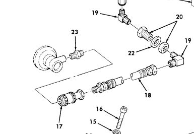
In order to make belt changing a little simpler, AM General incorporated using a quick-disconnect (Fig. 178, Item 17)  4730-01-399-0241 [4730013990241] on the hydraulic hose 4720-01-189-0853 [4720011890853]  leading to the fan clutch.

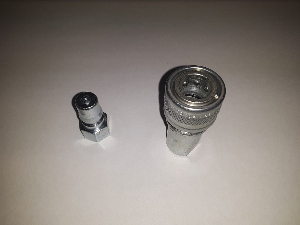
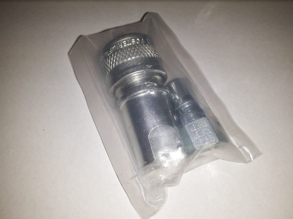
Although the quick-disconnect can be sourced as 12342947, it appears to now be marketed as an H1-62 coupler (a Parker number for the female half). This number is the female half of a 1/8″ hydraulic coupler. (Fig. 178, Item 17 actually depicts the male and female halves together) If you are lacking both parts, or if you just need to replace, search for an ISO-B hydraulic coupler in 1/8″ thread.

All couplers marked as ISO-B, regardless of manufacturer, should be interchangeable as long as they adhere to the ISO B standard (ISO 7241-B).

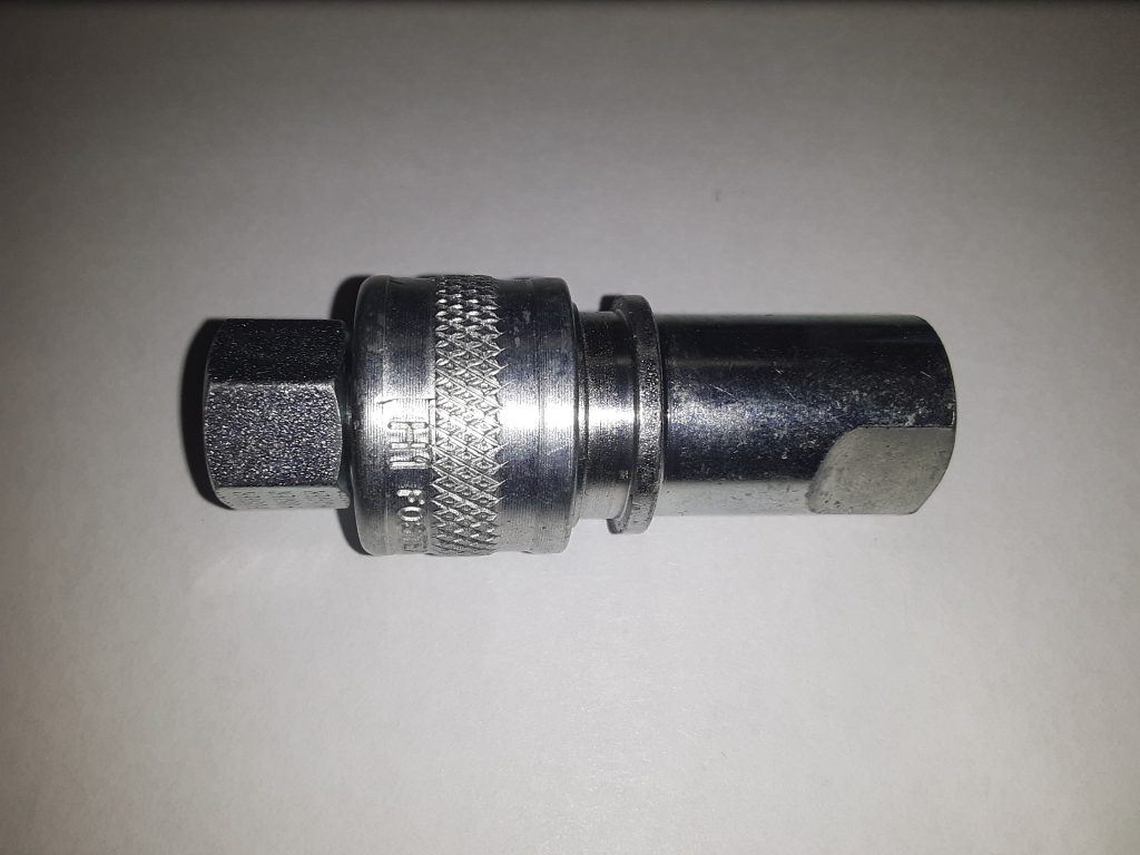
Above pictures are of Foster FHK Series 1/8″ H1S K1S Steel ISO B Hydraulic Quick Connect Coupler sourced from HPC in Elgin, IL.

A study in Steering Gear Bolts

As discussed in an earlier article, there are two 7/16-14 x 5.25 bolts 5305-01-213-4149  [5305012134149]  and one 7/16-14 x 4.00 5306-01-254-6356 [5306012546356] required to mount the steering gear to the frame. The 5.25″ length can be sourced as GM 9430761, however the 4″ bolt as MS35764-861 is not easily sourced, but 4″ long bolts are a standard length, unlike the 5 1/4″ length.

This article is about whether the length is that critical.  We do not believe so. (but read “word of caution” at end of article) For restorative purposes you may want the length to be as close as possible, or if not, to otherwise serve as a useful upgrade.

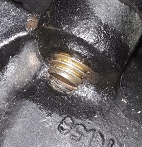
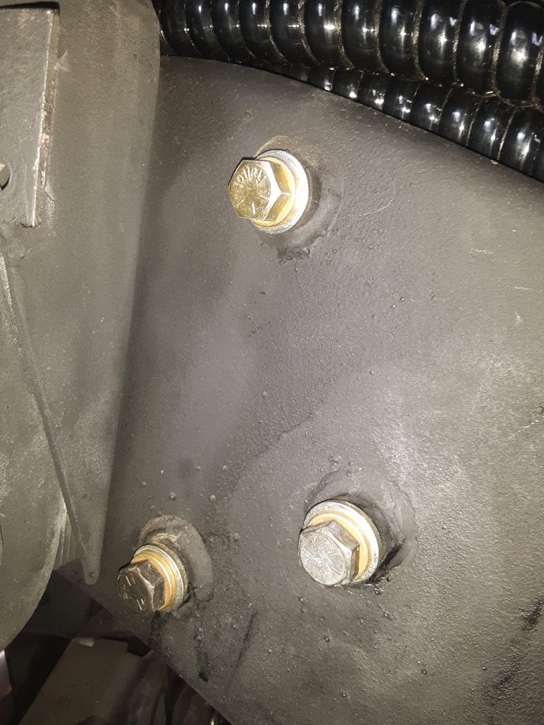
The picture below shows the clearance against the steering box when using the 4″ long bolt:
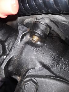
Note that the bolt extends through nearly 1/4″, and would likely have extended slightly further had we used a standard Grade 8 SAE washer instead of the “extra heavy” ones that we did. Further note that the end of the bolt can actually butt against the housing, the threads do not go above or across the top of the housing. Ensure that the end of the bolt does not butt up against the housing, which will result in a false reading with a torque wrench.

Note there isn’t a tremendous amount of clearance between the end of the bolt and the housing itself.  You can see that it was threaded into the housing so the bolt didn’t bottom out.

Ensure that whatever bolt/washer combination you use in the 4″ location that the bolt does not deadhead against the housing. (this would likely result in the upper boss of the steering gear not being drawn tight into the frame as well as causing an erroneous reading with a torque wrench.)

What about substituting longer or shorter bolts?

For the 4″ length bolt, the next shorter standard length would be 3 1/2″, and although that would at least partially engage most of the threads in the boss, we would advise against it except under emergency circumstances since this boss is the only one of the top two that even gets a bolt.

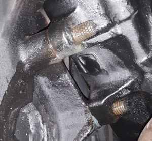
Our opinion changes slightly on the two lower 5 1/4″ length bolts.

In the picture above, you can see how far the 5 1/4″ lower bolts extend past the bosses in the steering gear. There is no doubt that a 5 1/2″ bolt might work (assuming the threaded section of the bolt is long enough and doesn’t bottom out in the boss).
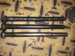
Pictured above are (top bolt), the sole 5 1/4″ bolt remaining in the M1038. The middle bolt is the GM 9430761 discussed above, and the bottom bolt is one supplied by one of the “big 3″ suppliers. The bottom bolt is in fact, a 5 1/2″ length bolt. Because we had concerns that the threads would not be long enough (and bottom out in the boss) we chose to not use the 5 1/2″ bolt and acquired the proper length of 5 1/4.” It is likely that people may have erroneously replaced this bolt with the incorrect length which could potentially lead to a dangerous situation.

In our opinion, the most rearward of the lower bolts could be a 5″ long bolt without any adverse issues. As we installed it, it is nearly 1/2″ past the boss. The frontward one could also likely get by with a 5″ length bolt and still thread completely into the boss.

A word of caution, however, is that the steering is one area you don’t really want to take risks in. You limit your liability and ensure vehicle safety by using the correct fasteners, or at least the correct length of fasteners called out by the manufacturer.
Steering Gear Mounting

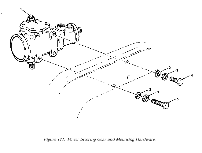
As luck would have it, the steering gear on our project M1038 had only one bolt holding it to the frame. Fig. 171 (of TM 9-2320-280-24P-1), shows two different bolts attaching the steering gear to the frame.

The sole remaining bolt was 5 1/4″ long. According to the call out in the Parts Manual, this corresponded with Item 5,  5305-01-213-4149 [5305012134149].  Unfortunately, however, it was virtually impossible to locate a 5 1/4″ Grade 8 bolt, as the common sizes are 5″ or 5 1/2.”

Although some of the “big 3” indicate that a bolt kit is available for the steering gear fasteners as 5745684, when we ordered it, we were told it was on backorder from AM General, and at least one seller indicated that the kit was simply “discontinued.”

We cancelled the backorder and tried sourcing again. We were able to find a seller on eBay selling “GM Hex Head Cap Screw Bolt 9430761  7/16″-14 x 5.25 Grade-8 UNC.”

As it turns out, 9430761 is the manufacturer’s part number for this bolt, and being as it is a GM steering box, it makes sense that GM would be the supplier. Although we had to purchase five bolts, when we technically only needed one (there was one remaining), we have extra bolts in the event they are needed in the future by us or others.

The callout for the remaining bolt (Item 4) is 5306-01-254-6356  [5306012546356] which is described as: “BOLT, SELF-LOCKING 7/16-14 X 4.00″  Although 4″ is a common length, we were not able to source this specific bolt (MS35764-861) and substituted it with a standard 7/16″-14 x 4” Grade 8 bolt.

It is not uncommon for steering boxes to loosen up over a period of time. We originally opted to use Nord-Lock lock washers in place of the split lock washer. However, in the interest of attempting to keep the project as original in appearance, we instead used Grade 8 split lock washers and heavy 7/16″ Grade 8 SAE washers instead. All three bolts were installed with blue loctite and torqued to 60 ft-lbs.

Torque specifications and use of blue Loctite are as recommended by flashoffroad.com in their chart located at:  http://www.flashoffroad.com/Maintenance/Specs/torqueSpecs/HMMWVTorque.htm  (opens in new window)

Installation of the RH Front Brake Line

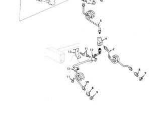
The front brake lines on the 1038 had already been scavenged prior to our restoration of it.  After ordering the proper brake line 4710-01-186-1016 [4710011861016] also known as 5584142 (Fig 159, Item 10), and going to install it, it was somewhat confusing based on the parts manual.

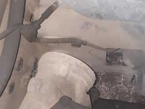
From the parts manual, it appears Item 10 goes in front of the crossmember.  However, after researching brake lines on the 998, we learned the tubing starts on the rear side of the crossmember and loops through to the front side as indicated in the following picture.

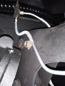
Below is the front RH brake line mounted in the M1038.

Note the use of the 3/8-16 self threading screw (or bolt) 5305-01-236-4349 [5305012364349] discussed in another article.

The lesson is exploded views in the parts manual are not always accurate. A big example of these inaccuracies is the rear vent lines (Fig. 149), which appear to have been flipped left to right. We will address these discrepancies in another article.

Interchange: Fan Solenoid Mounting Clamp to SAE Size Hose Clamp

Both the fan control solenoid and mounting clamps had already been scavenged from the 1038.

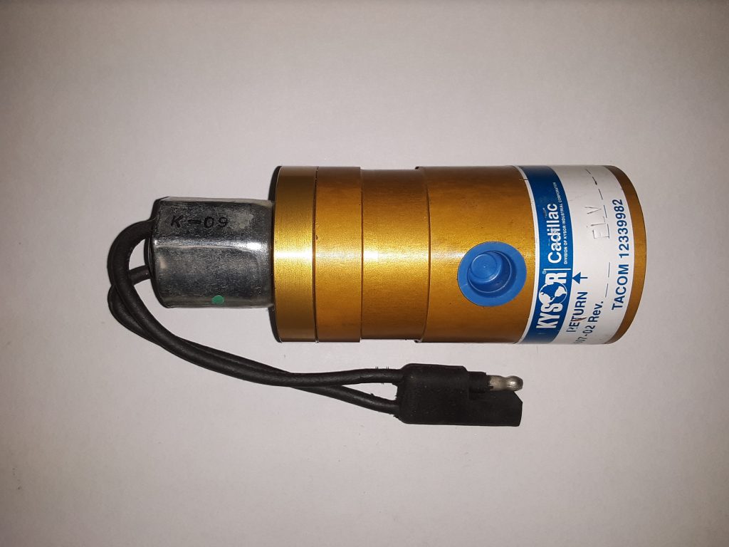
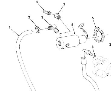
Finding a replacement solenoid (Fig. 177, Item 5) 4810-01-192-5817 [4810011925817] was relatively simple, and just about every supplier stocks it.

It would be nice to find a cost-effective substitute, but as of yet, we have not located one that would be both cost-effective and a simple retrofit.

The clamps holding the solenoid to the body were also missing. The parts manual (Fig. 177, Item 6) does a call out for 4730-00-204-3491 [4730002043491] but fails to specify its size.

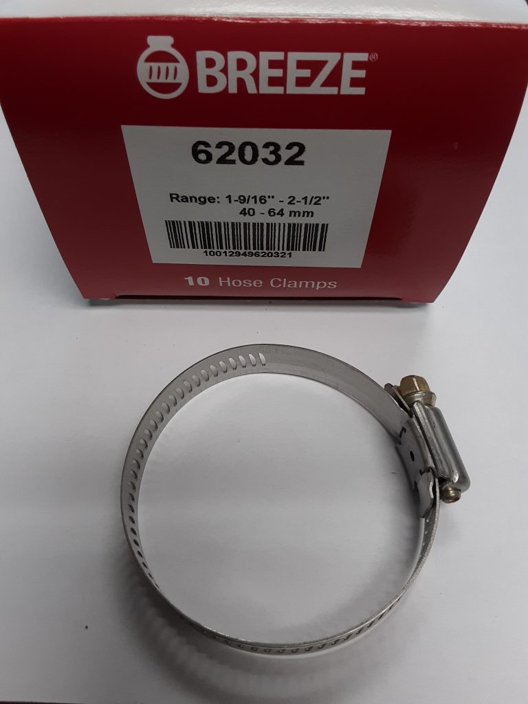
After researching the NSN and manufacturer number of C32P, we identified this clamp as a 40-64mm or (1 9/16″ to 2 1/2″) stainless gear clamp. This clamp is an SAE 32 hose clamp. We acquired a box of ten Breeze brand clamps for our application, although only one is required. In fact, it appeared during our research that Breeze or its parent company may have actually been suppliers of this clamp to the government as 4730-00-204-3491.

The Rear Spring Clips, or “Why so expensive?”

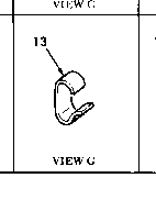
Without a doubt, on a weight basis, these are the most expensive part of a HMMWV. The Parts Manual calls out for six spring tension clips 5340-01-209-7808 [5340012097808].

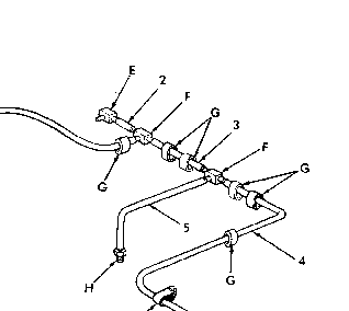
Figure 149 showing location of CLIP,SPRING TENSION REAR (“G”)

We were only able to source these clips from a single vendor, and they wanted over $10.00 each plus shipping. We sent RFQs out, and prices came back as high as $35.00 each. We then searched brake clip and fastener vendors to see if we could identify a cheaper source or a suitable substitute and were unable to locate any.

The only purpose these clamps serve are to attach the vent lines from the hubs and differential to the brake lines to keep the vent lines from becoming detached or torn off. We found a suitable (but not necessarily authentic) method of attaching the vent lines to the brake lines.

Although we would have preferred to use the proper clamps, the end result is virtually the same. Spending $60 to $210 for the proper clamps in these locations simply was uneconomical and would have made no sense. Should we locate a source for these clips or a more suitable substitute, we will update this section. Needless to say, these clips are not visible once the body is installed.

Keep in mind, however, cable ties are not totally incorrect for a HMMWV. There are several call-outs in the parts manual for use of cable ties (e.g., STRAP, TIEDOWN, ELECT 5975-00-074-2072 [5975000742072] — used to hold hoses together).

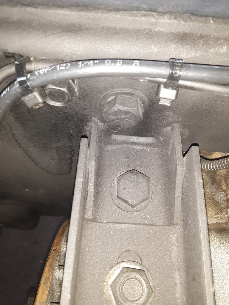
Vent Tubing: Hub, Differential, Transmission and Transfer Case

Our project vehicle had been stripped of most of the vent lines, and some it appears may never have been correctly installed.  (See: missing fitting and hose on front differential vent caused water infiltration).

Accordingly, we had to source and locate replacement or substitute hose and tubing for installation. All of the hoses and tubing are indicated in the parts manual as either P/N CPR104420-1 or P/N RB1450-1-4IDX1-20D. 

Upon visual inspection, CPR104420-1 was identifiable as air brake tubing used on semi-trucks. One of the brand names for this is an Eaton product called Synflex®.

Synflex® used to vent rear differential and hubs and transfer along frame. 

Upon further research, it was determined that CPR104420-1 is 1/4″ diameter tubing. (note this tubing is measured by O.D., not I.D.) Whereas CPR104420-2 is 3/8″ diameter. (CPR104420-2 is used as the main tube running parallel to the frame to vent the fuel tank).

We were able to identify RB1450-1-4IDX1-20D as being manufactured by Armstrong, and carries an NSN for bulk lengths as 4720-00-684-4033 [4720006844033].  This essentially is a durable 1/4″ I.D. hose, which has the appearance of 1/4″ fuel hose or similar.

There is a number of vendors that make a suitable replacement, although we noted the caveat of not using fuel line because it may not remain flexible enough over time for use on the front hubs. (they will constantly be flexing as the vehicle is steered).

It was suggested to us to consider use of silicone vacuum or vent hose.  Silicone hose was simply not readily available at the time of manufacture and design of the HMMWV. Vendors cautioned against using silicone hose for oil or fuel carrying. The primary reason for not using silicone for fuel is that it simply isn’t rated for pressurized fuel. We determined that 1/4″ silicone hose would be appropriate for venting purposes, and noting its widespread use in commercial and agricultural applications gave us a level of comfort of its reliability.


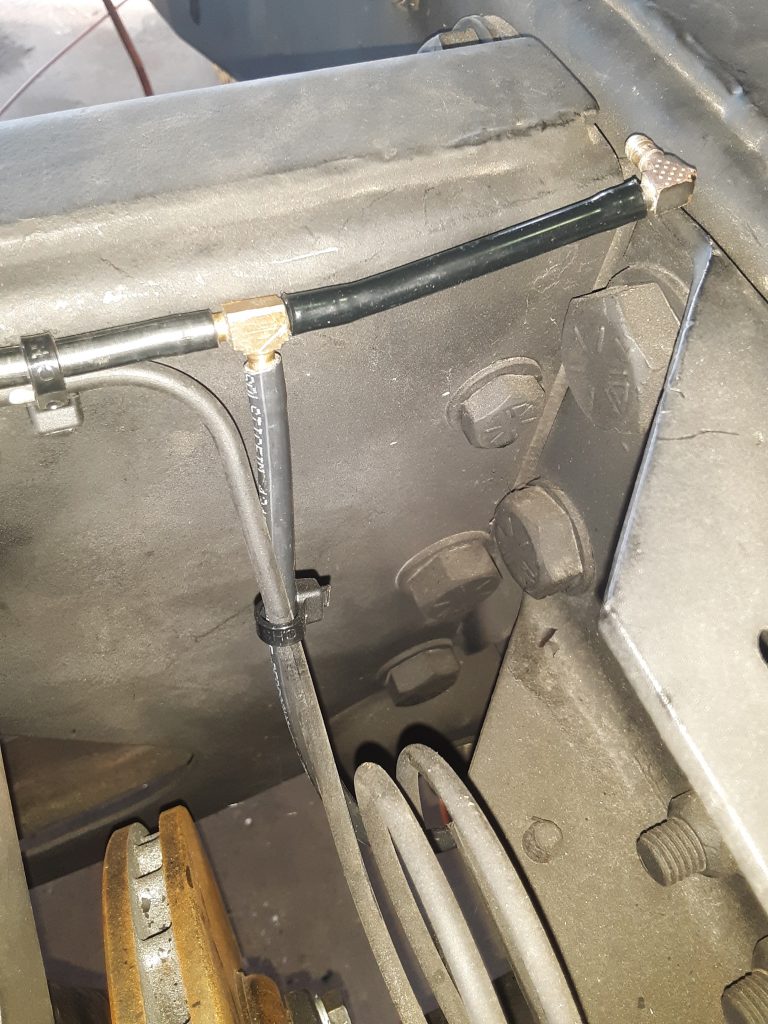
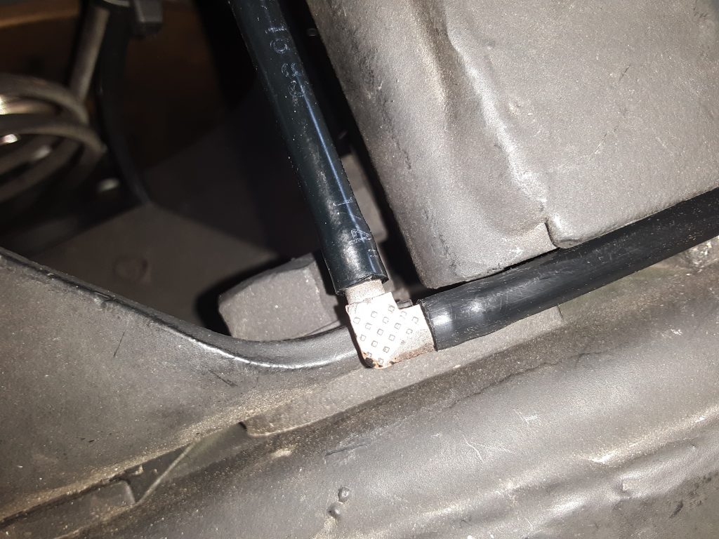
Front RH vent line from hub attached to tee fitting on frame. Note use of original style clamp 4730-00-954-1251 [4730009541251]


David Clark(s)

The inside of HMMWVs are extremely noisy. The engine sits between you and the front passenger, and sometimes even yelling across the hump isn’t enough to be heard.

My brother decided to address this by adding David Clarks to both protect your ears and provide a more sensible way to communicate.