As our shifter was frozen solid, it required use of a hydraulic press, hammer, and punch to dissasemble the shifting mechanisms. In the process, we ended up destroying both the shaft and the bushing.
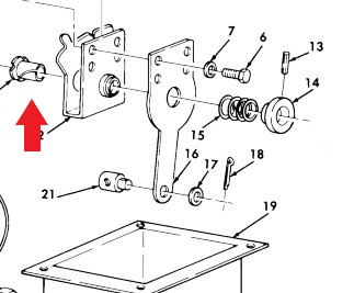
This bushing 3120-01-191-3232 [3120011913232] (indicated by red arrow) is made of thin nylon. Although after looking at it, we could have replaced it with an oilite or brass bushing, that would require machining of the shifting bracket. We then attempted to source the bushing using the NSN with no luck. However, we were able to located the part (currently available for order) from the manufacturer using the part number 10L18F. Applied Industrial Technologies carries this part available at https://www.applied.com/c-brands/c-thomson-industries/10l18f/Thomson-Nyliner-Bearing/p/101610126.
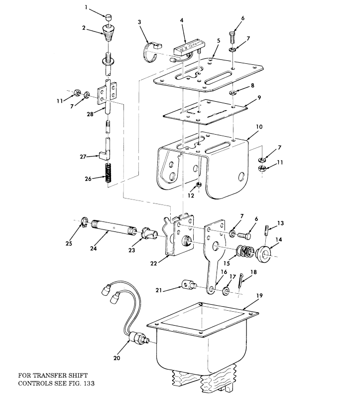
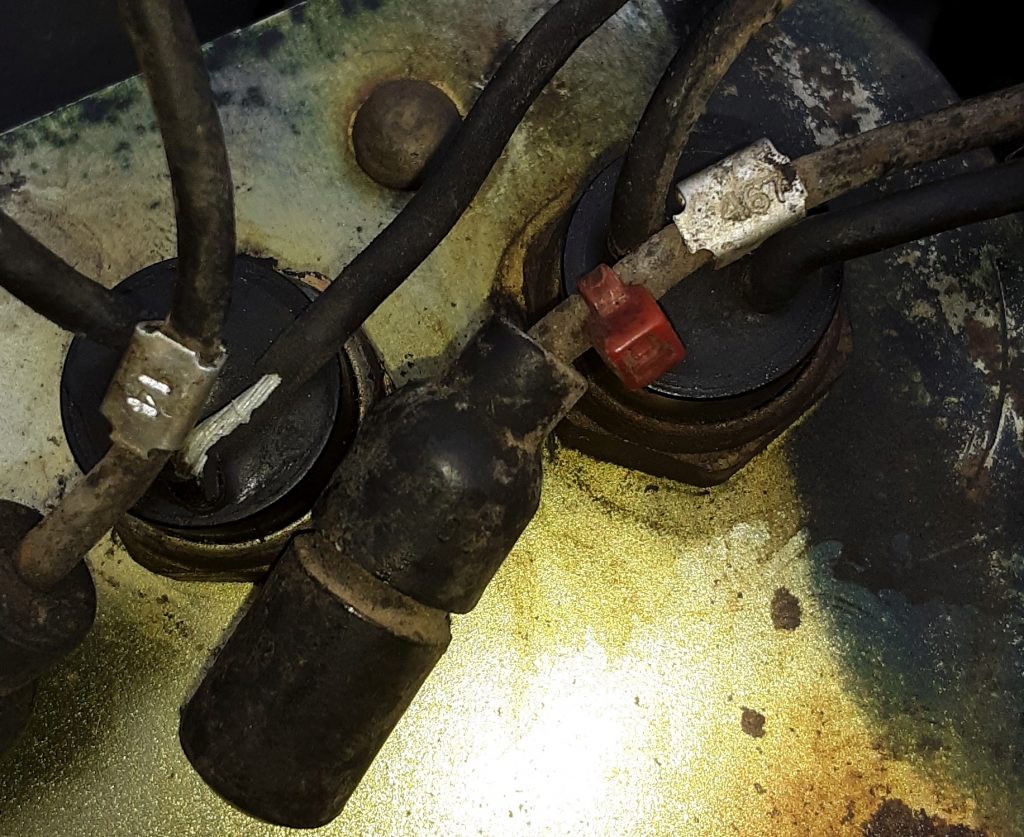
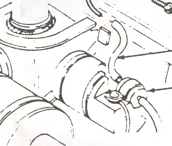
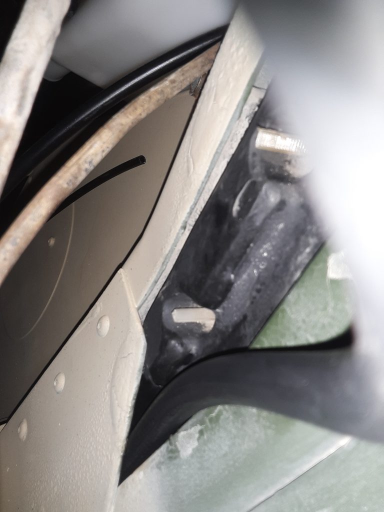
The transmission shifter in our M1038 was frozen, in that the release button could not be depressed to release the shifter. Additionally, the lever 2520-01-189-1064 [2520011891064] (Fig. 99, Item 16) was broken at the connection point. After removing the entire assembly, we noticed that this was an atypical shifter in that it had not only the safety switch 2920-01-249-3492 [2920012493492](Fig. 99, Item 20), but also a reverse light switch (not shown in diagram).
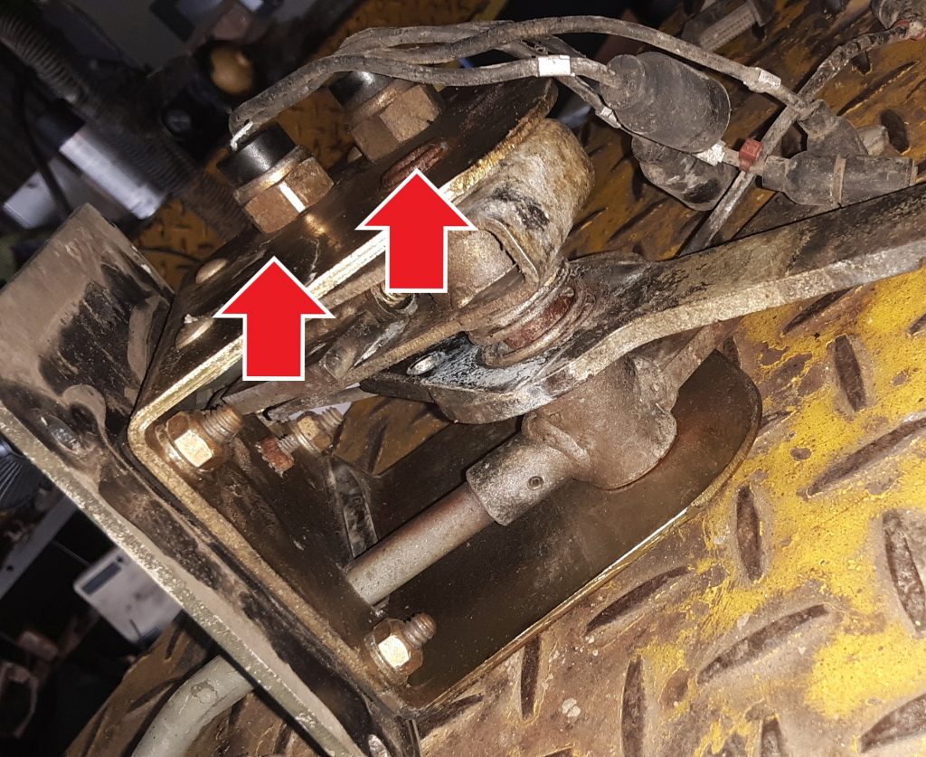
Shifter showing neutral safety switch and reverse light switch. Reverse switch is the right arrow.
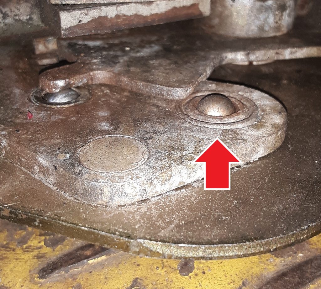
It is our current understanding that the reverse light switch was used only on Marine HMMWVs, but that it is also desirable for on-road civilian use in states that require a functioning reverse light. The lead from one of the wires was 467 (whereas the neutral safety is 14). Of note, the hole for the reverse switch appears to exist in all of the housing assemblies (Fig. 99, Item 10). (See diagram). Of further note, the switch appears to be the same as the neutral safety other than there is a bushing installed to allow the smaller switch to be installed in a larger hole
From this, it appears that a reverse light switch can be installed in any of the earlier shifters. Once we identify the threaded bushing dimensions, we will post it. It seems relatively difficult to source the reverse light switch as opposed to the neutral safety switch.
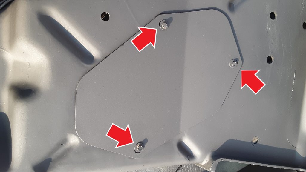
When installing splash shield supplemental armor 9515-01-189-9728 [9515011899728] to the left hand splash shield, it is required to eliminate the access cover 5340-01-457-0459 [5340014570459] by removing the three screws 5305-00-115-9934 [5305001159934] (MS51849-55) indicated by the red arrows that attach the access cover to the splash shield.
Failure to remove the access cover when installing the supplemental armor will result in an incorrect fit, and possibly damage to the splash shield. Additionally, the access cover cannot be accessed because it will be blocked by the armor.
The HMMWV uses a common cooler frame containing cores for both transmission fluid and engine oil. 2930-01-168-7911 [2930011687911
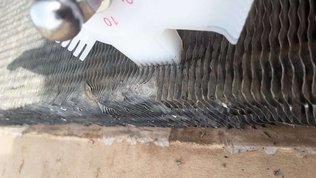
Cooler fins being straightened with a Robinair 18403 Fin Comb (also known as a “fin straightener) Note the use of the 10 fins/inch com
Quite often, the cooling fins are damaged (by being bent or collapsed) at the top and bottom of the unit, and often within the main area of the cores themselves.
Our unit had crushed and bent fins on the top, bottom, front and back. The picture above shows use of a fin comb to straighten out the fins. Although we used a Robinair with multiple combs, you could simply acquire a 10 fins/inch comb to accomplish the same task.
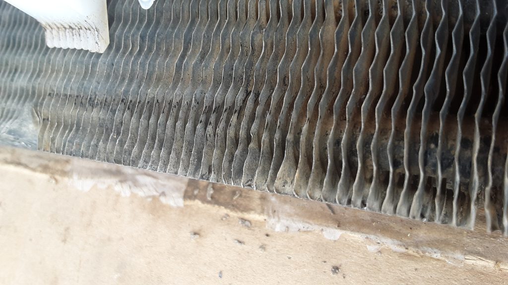
Although a tedious and time consuming task, this will ensure not only optimum airflow and cooling, but it also eliminates the somewhat unsightly bent fin situation.
Cooler shows straightened fins after passes with fin comb.
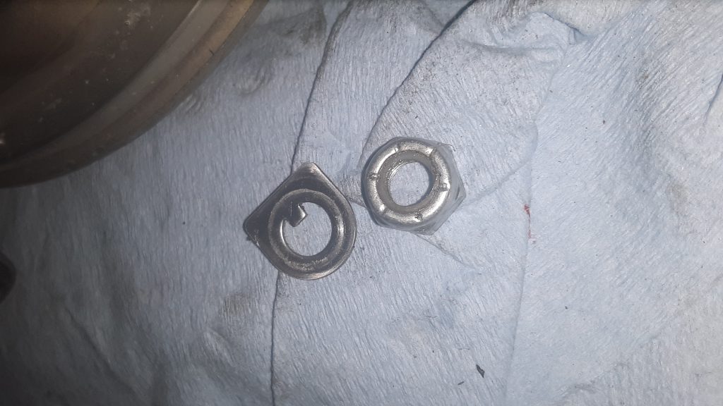
The first step (once the fan clutch has been removed from the engine) is to remove the lock nut 5310-01-194-0481 [5310011940481] and locking tab 5310-01-189-8468 [5310011898468] from the face of the cylinder assembly 2930-01-189-1744 [2930011891744].
Self locking nut and locking tab from front of fan clutch
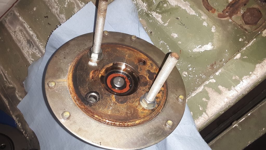
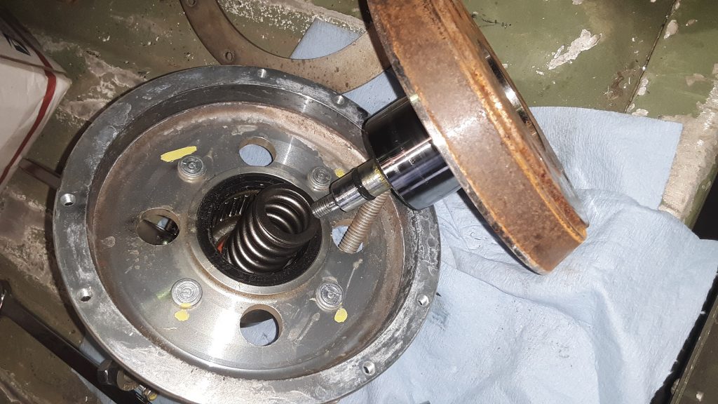
Next, install two 3/8 x 5″ (or so) bolts as shown below and tighten the shaft assembly 4079-38441-01 (no NSN) into housing assembly 4040-38442-01 (no NSN) enough to release the spring tension to remove the six capscrews 5305-00-052-6456 [5305000526456] holding the back plate on . Remove the backing plate. Do not, under any circumstance, remove the backing plate screws without a method (such as the bolts indicated in the picture) in place. There is a spring under pressure and failure to properly restrain it can lead to serious injury or even death.
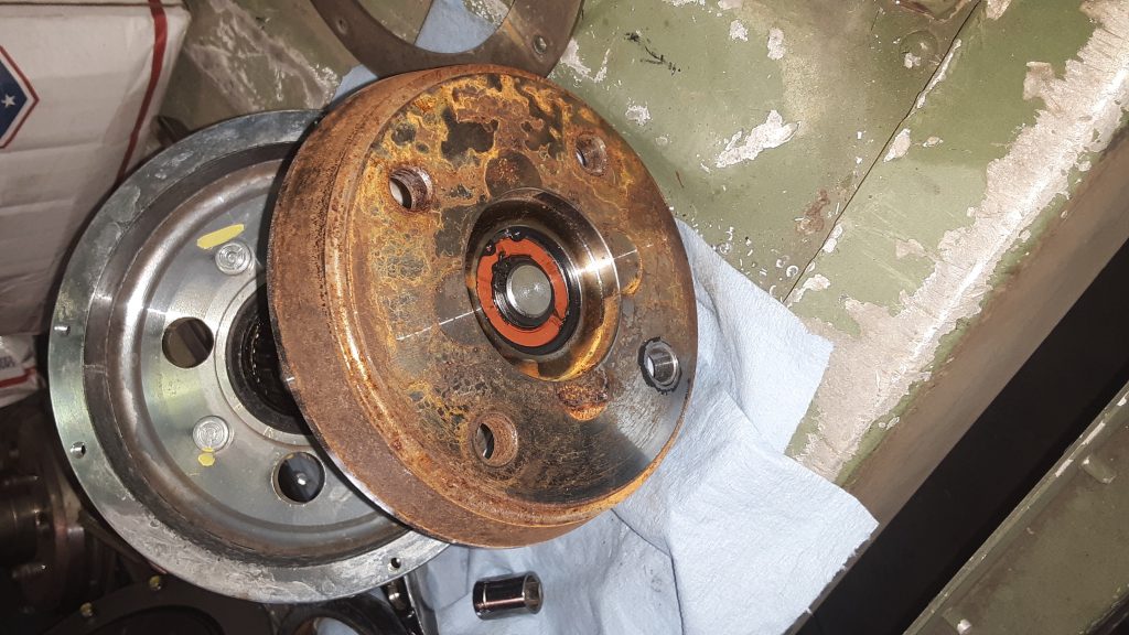
Once the backing plate is removed, the clutch lining 2930-01-189-8643 [2930011898643] can be removed. It is not uncommon to stop at this phase, if the problem was that the fan wouldn’t DIS-engage because the lining had “frozen” to the shaft assembly. If not being replaced, the lining can be cleaned up using emery cloth or similar. The clutch surface of the shaft assembly can also be polished in this manner.
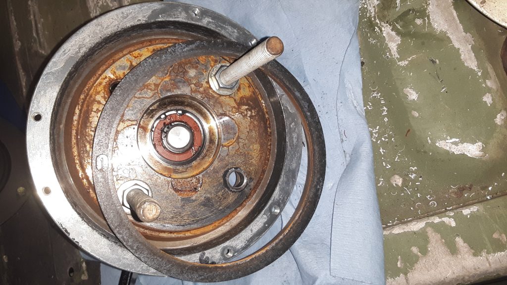
Friction lining removed, shaft assembly under spring tension (held safely by 3/8 bolts).
Once the spring pressure is completely relieved by slowly releasing tension on the safety bolts, the safety bolts can be removed. Inspect the inner bearings as well as the Torrington-style bearing and seals. Replace any damaged parts.
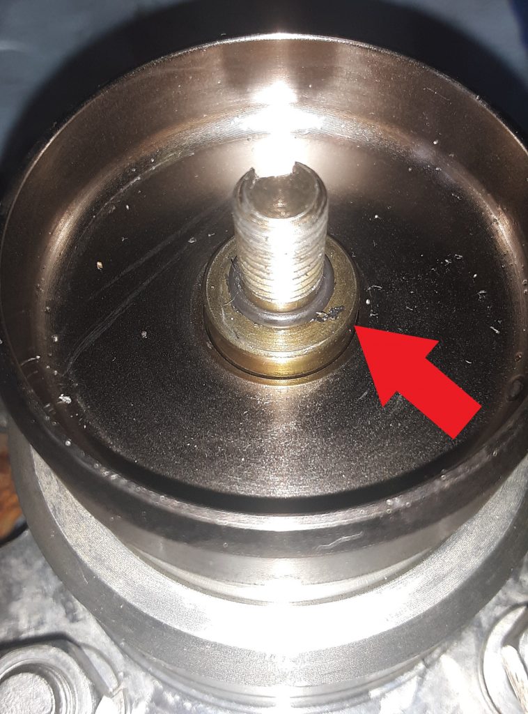
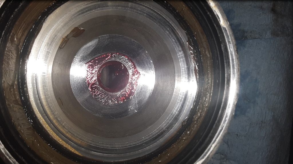
The below view shows the spring, seal and inner bearing. Ensure all O-rings are serviceable, and that the bearing surface on the shaft assembly is not damaged.
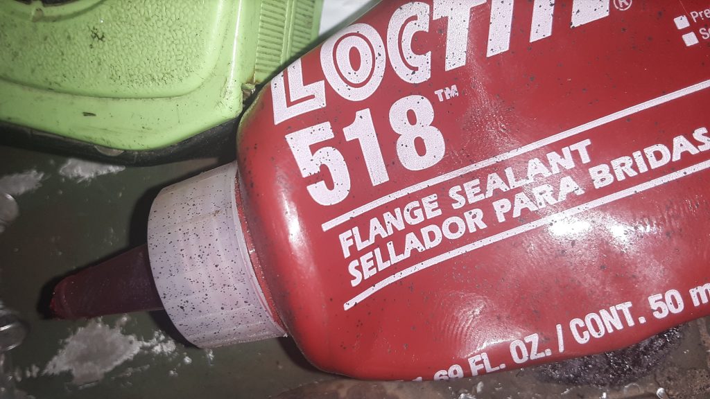
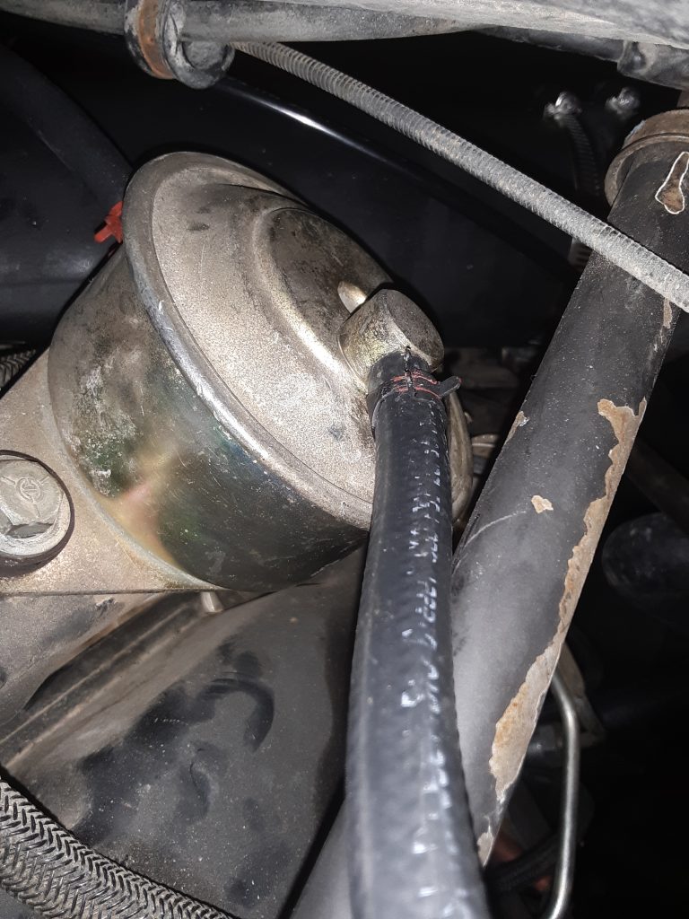
On reassembly, there is often leakage at the front O-ring, even when a new O-ring is used. Because of the likelihood of leakage, we recommend use of Loctite® 518 (or similar) on the sealing surface indicated by the Red Arrow in the picture below, as well as the corresponding location.
Reassemble the entire unit as it was disassembled. Again, Use safety precautions during reassembly because you are putting a lot of potential energy into the spring as it is tightened. Improper assembly can potentially cause serious injury or even death. If you have any doubts, please refer this to a professional or person experienced in assembling spring loaded machinery.
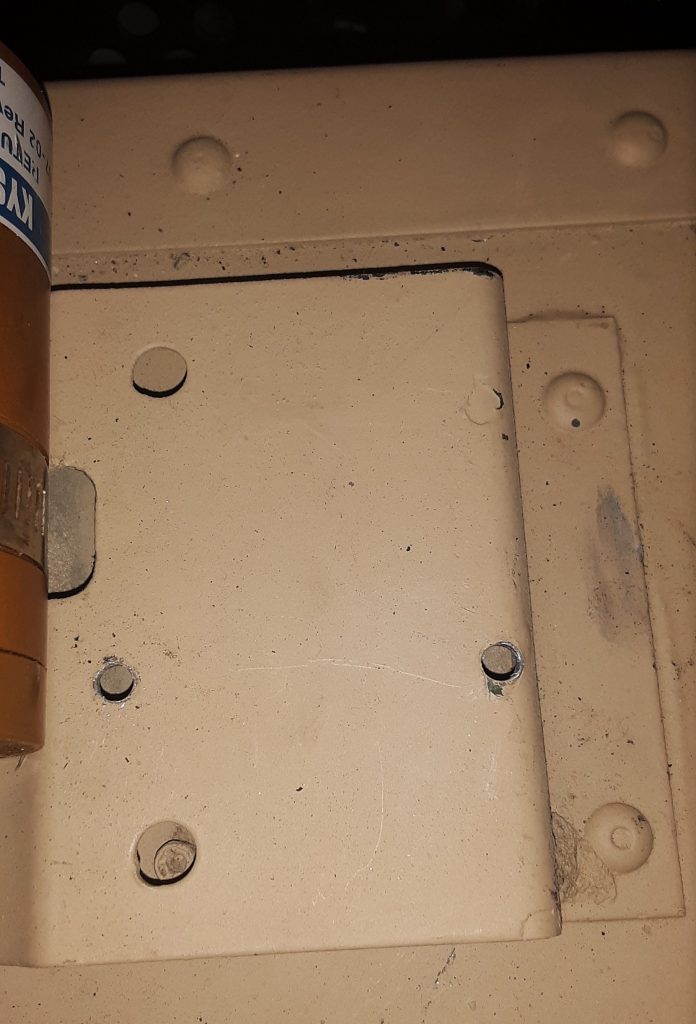
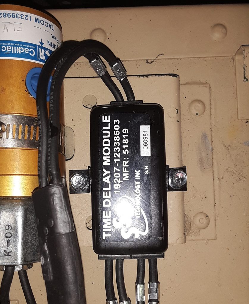
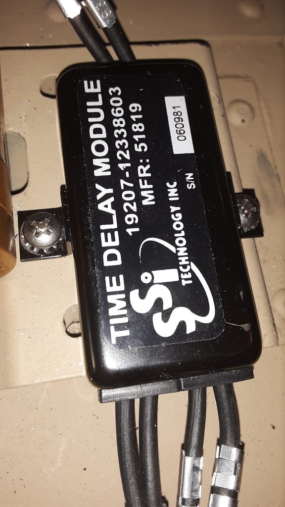
It is not uncommon, when replacing the Time Delay Module, to encounter stripped mounting holes. This is primarily because the mounting surface is aluminum, and people often overtorque the screws anyway. We attempted to use #10 sheet metal screws to mount the Module, but there was insufficient material to hold the screw.
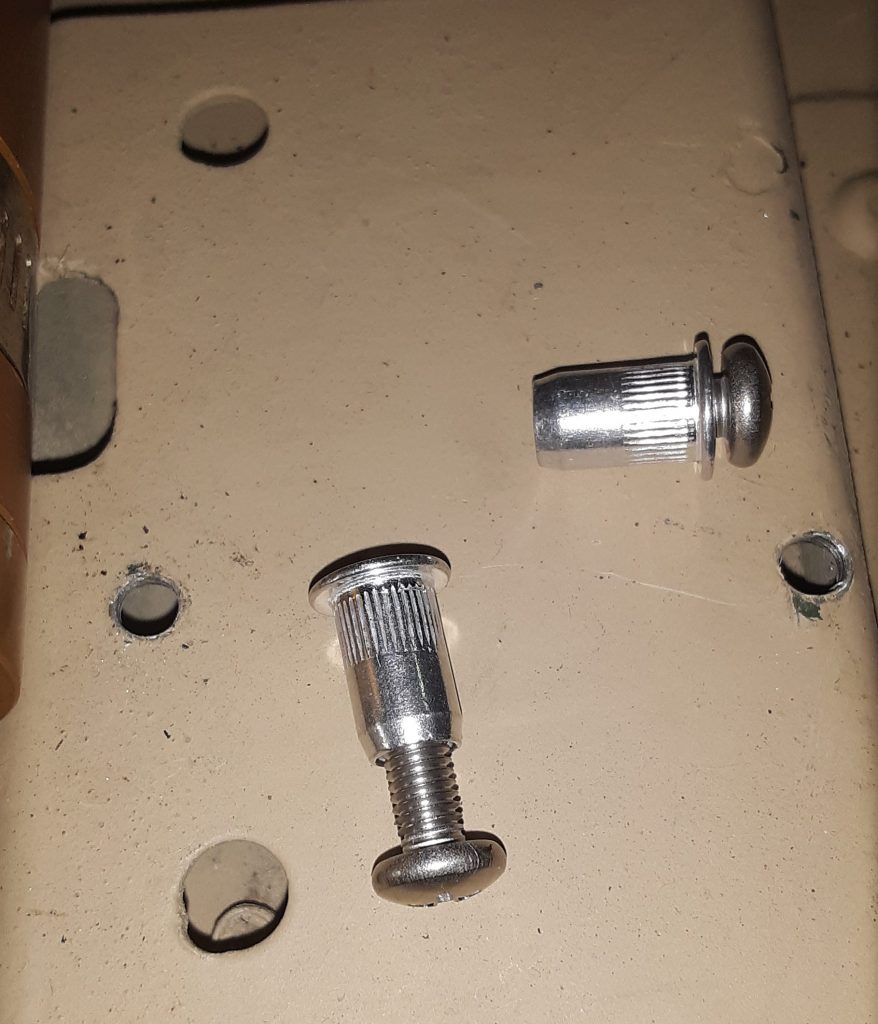
We initially attempted to use 10-32 x 1/2″ flanged screws with washers and nuts on the underside:
As you can see, the rearward screw cocks sideways. Although functional using the nuts on the backside, it was extremely difficult to accomplish, and would not be “user-friendly” when and if replacement was necessary. We removed the Module and decided to use rivet nuts (“nutserts”).
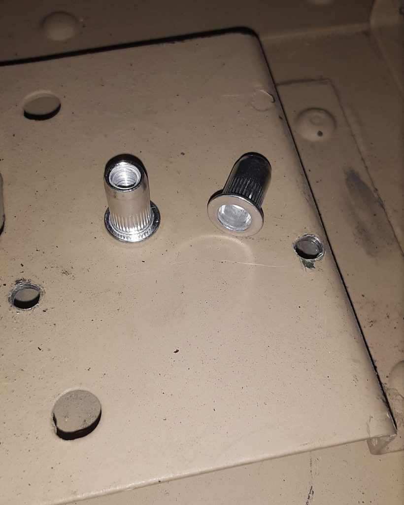
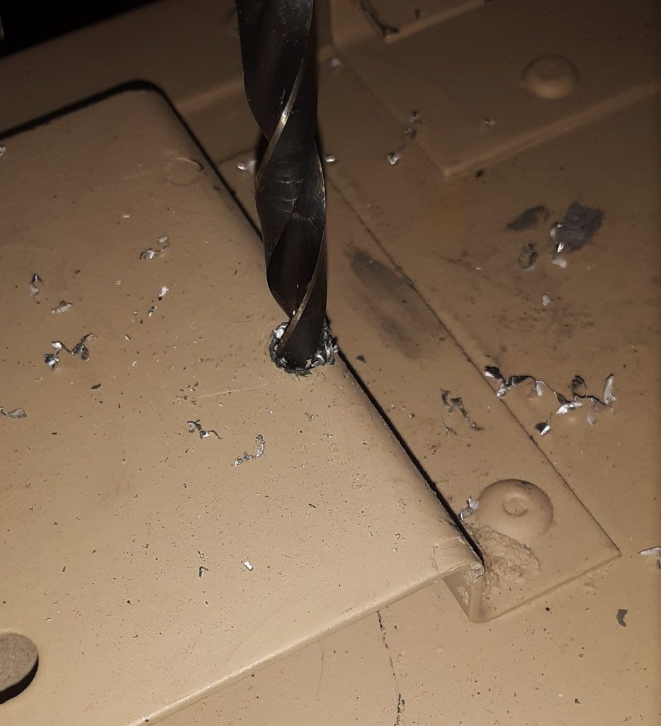
We intend to use 10-32 x 1/2″ screws, and acquired 10-32 rivet nuts intended for thin or sheet metal. The holes need to be drilled out to the outside diameter of the rivet nut.
Next, confirm the rivet nut is threaded correctly by inserting the screw into the rivet nut.
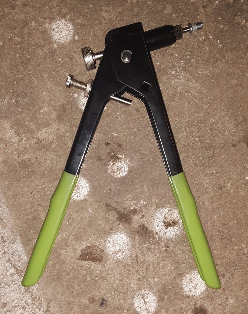
Next, thread the rivet nut onto the rivet nut gun and crimp into the drilled holes.
Once again, thread the intended screw into the crimped-in rivet nut to confirm threads are undamaged.
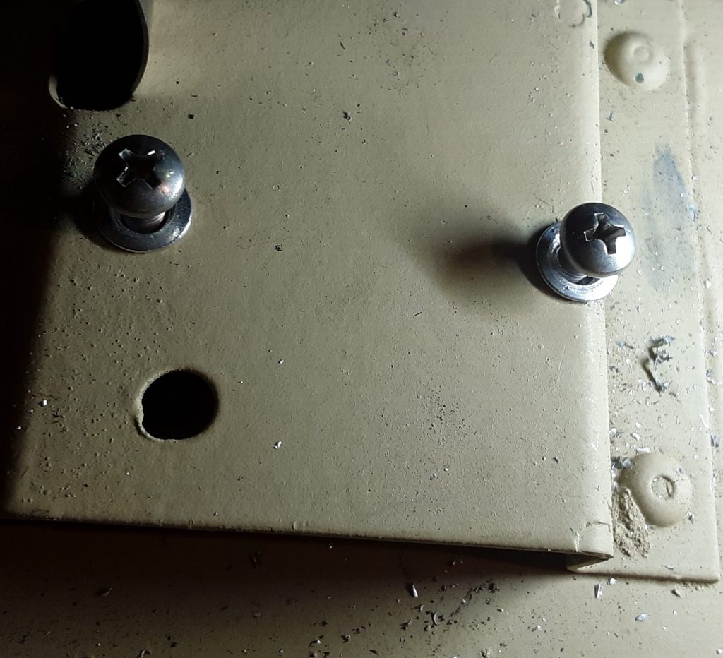
For final installation, we installed stainless steel screws and placed star lock washers to ensure they will not back out during operation.
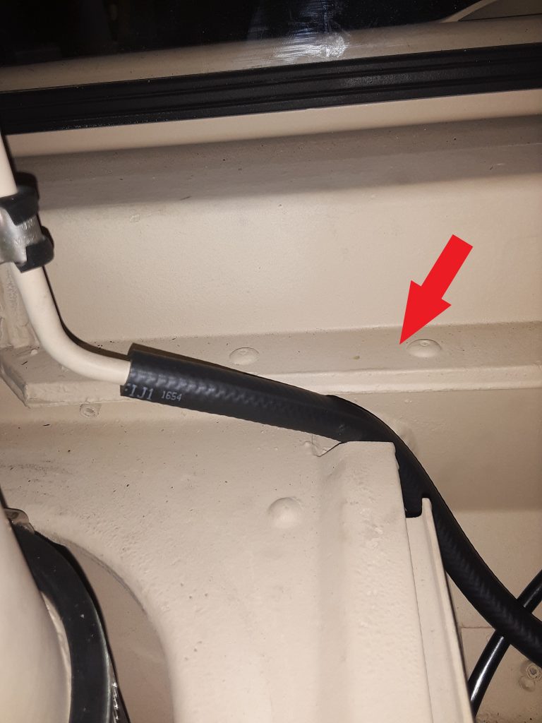
Hose is Figure 398, Item 30. (The Corbin clamp is not on the vent tube at time of photo)
The arrow in the photo above indicates the position where the vent hose leading from the fuel tank vent line filter 2910-01-210-5872 [2910012105872] (behind the surge tank) is to be placed for clearance when the hood is closed. Note a Corbin style clamp 4730-00-954-1251 [4730009541251] needs to be placed on the hose ends both where the hose attaches to the tube and to the filter.
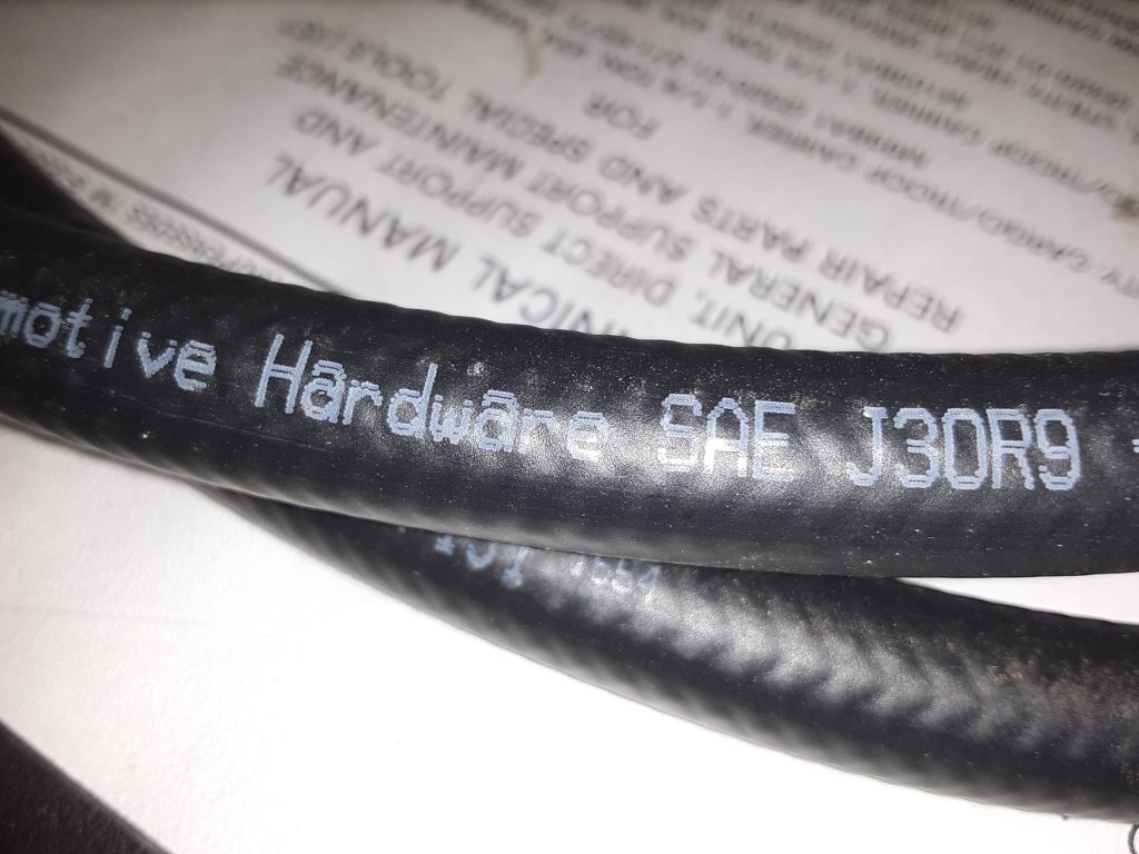
The callout for this hose is for an 11″ length of CPR104420-2 (replaceable with 3/8″ air brake tubing, such as Eaton Synflex®). We instead replaced this with 1/4″ SAE J30R9 hose (which we consider a modern and equal substitute for RB1450-1-4IDX1-20D).
Our reasoning for using hose instead of tubing is based on a couple factors: First, it is called out as RB1450-1-4IDx1-20D (or equivalent) to connect the fuel tank vent line to the fuel vent line filter (See Figure 18, Item 6). We are of the opinion the hose leaving the vent line filter should be the same as the hose entering the filter, and that indication of tubing may be an error in the TM. Second, use of air brake tubing essentially requires a heat gun to soften the tubing enough to slide over the tube on the stack and bead on the filter itself. Although this can be accomplished, should field repairs be necessary, it essentially requires cutting the tubing, where the hose can be easily removed by loosening the Corbin clamps.
Note: the drawing indicating the vent line hose appears to be the same as the hose entering the vent, and does not appear to be tubing. Although this may be based simply on the artist, we are of the opinion that the hose leaving the vent should be the same as the hose entering the vent.
We note the installation instructions for the DWF kit also indicates the CPR104420-2. See http://www.hummerknowledgebase.com/driving/dwf.html (at Image 3), where is specifically calls out an 11″ length. (We do, however, note this document is extremely dated, as it calls out for use of Dexron II at Image 5). Dexron II was long ago deprecated: In 1993, GM released new Dexron-III fluid (GM Spec GM6417M and later GMN10055). As noted above, we believe the J30R9 hose is made from material superior to what was available during original engineering of the HMMWV. and stand by our recommendation to instead use J30R9 hose.
Although we have no way of knowing at this time, there may have been a UV (sun) resistance issue where the engineers preferred the air brake tubing over the hose for that reason. It may well be that the CPR104420-2 tubing has a greater resistance to breakdown that the RB1450-1-4IDx1-20D hose. However, we are around 30-some years since the original design, and materials have changed. We will monitor the J30R9 hose to determine if it exhibits any undesirable weathering characteristics.
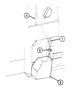
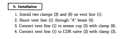
The above figure appears as if it is a straightforward task to insert the cup sensor to CDR vent hose (No. 1 in picture).
In fact, even the instructions, Sec. 12-13 (TM 9-2320-280-3) makes it appear that you simply have to “route vent line through “A” beam.”
It truly is not a simple task. Ours being a Marine unit seems to be lacking in most of the insulation. It did, however, have the insulation installed inside the “A” beam. We erroneously made the assumption that since our HMMWV was originally equipped with the fording system, it should be as simple as the manual indicated. We spent several hours trying to thread the hose from both the top and the bottom with no success. The hose would consistently stop around the halfway point.
After running the lift up and down a number of times, we decided to see whether we could “fish” a piece of 3/8″ air brake tubing through the pillar. Although it took considerable effort, we were able to push the brake tubing completely through. We then connected the tubing to the hose with a 1/4″ hose barb and attempted pulling the hose through. That method failed on several tries.
We were ultimately successful using pure silicone (silicone gel for waterproofing / rubber boots, etc., not RTV) to lube the end of the hose and about half way up. The hose easily slid through. We suspect that there was just too much friction where the hose was somewhat pressed against the insulation.
Being that we have a crate of circa 1960 Dow Corning military surplus silicone, there was no cost. However, in the event you aren’t oversupplied with silicone gel, we strongly suspect that tire bead lubricant or even dishwashing soap would also serve as well.
View of CDR to Sensor Cup vent line as it enters top of RH “A” beamView of CDR to Sensor Cup vent line connected to CDR. Note routing of vent line across top of transmission dip stick tube. (this tube will be replaced with a DWF tube)
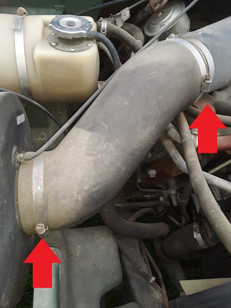
Arrows indicating locations of three hose clamps 4730-01-189-0871
Based on the call-out from the parts manual, the three hose clamps indicated below are 4730-01-189-0871 [4730011890871] or manufacturer number H68SS. Upon our research, these part numbers cross over to an SAE 68 hose clamp. Unfortunately, while size 68 clamps can be located, they are not generally commercially available. The standard (and readily available) sizes are either SAE 64 or SAE 72. We ordered both.
As it turned out (and we will post a picture later), SAE 64 is the perfect size for these three locations. We have noted that the specifications almost always call out a hose clamp considerably longer than necessary, and often leaving too much of a “tail” to grab debris, bend, and cut hands. (See photo below).
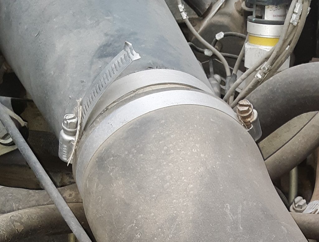
M998 Air Cleaner hose clamp showing excessive “tail” when called out part used
This hose clamp was unmodified and as received from the military. Based on what we could tell, this was a SAE 68 hose clamp.
We ordered the SAE 72 hose clamps to interchange for the clamps called out 4730-00-359-9487 [4730003599487] for use on the fording elbow 4720-01-194-5338 [4720011945338]. Although we have not yet installed these clamps, we predict they will have a considerable tail. However, those hose clamps are (for the most part) not quite as visible. On visual inspection, it appears that the SAE 68 (and possibly SAE 64) clamps may also be appropriate at that location. We will update should this information be found incorrect.
In several earlier posts, here and here, we discussed a suitable substitute for Armstrong Hose RB1450-1-4IDX1-20D. We stand by our opinion that 1/4″ silicone hose is appropriate for the vent hose from the front hubs to the tubing.
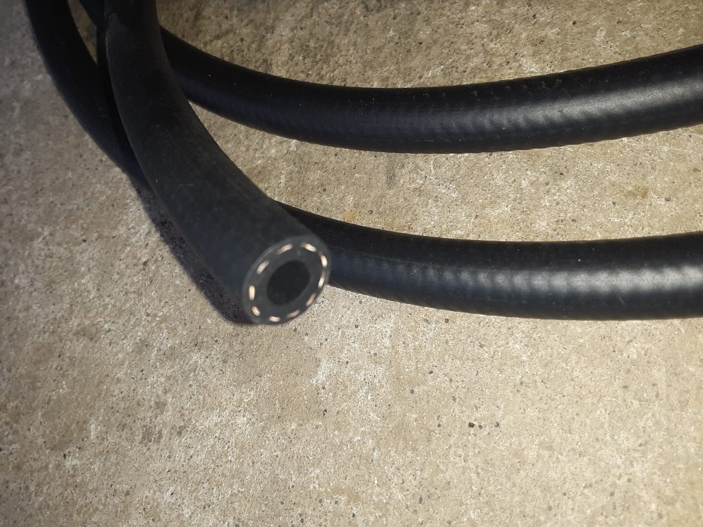
We received and installed the SAE J30R9 hose (fuel injection hose) for the underhood Deep Water Fording (DWF) applications of the fording valve 4820-01-192-8030 [4820011928030] to CDR valve 4820-01-192-7678 [4820011927678] and the sensor cup 2540-01-192-4502 [2540011924502] to CDR valve.
Pictures below are of the J30R9 hose utilized:
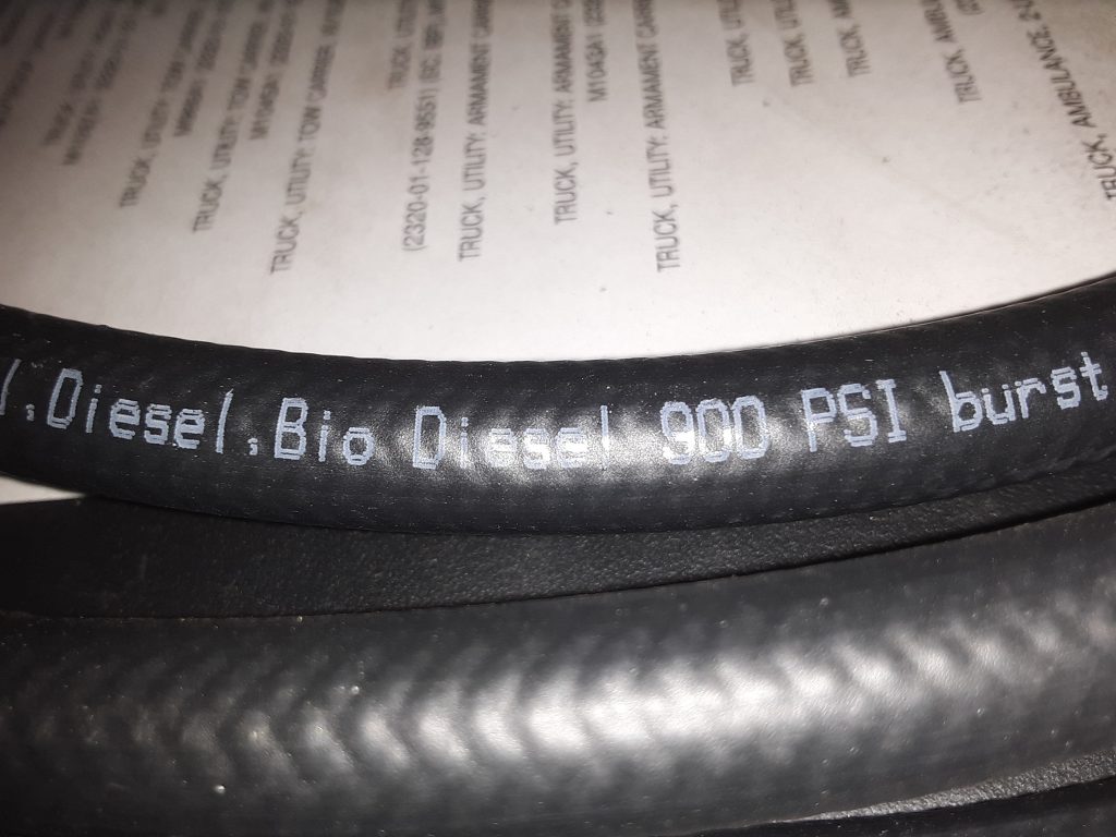
As noted in the earlier posts, this hose is rated at 100 p.s.i. operating pressure, and bursting pressure of 900 p.s.i. We feel this is more than adequate for venting purposes, and appears to be made out of more modern material that is specifically rated for diesel and bio-diesel (as well as other fuels).
SAE J30R9 hose labeled for use with Diesel and Bio Diesel
As a further note, we will be reviewing whether we also wish to replace the general fuel lines with this hose, as we noted during our review of the M998 that it was using SAE J30R7 hose. As we noted in an earlier post, we were denied sale of J30R7 hose to California ostensibly because J30R7 hose has too high of a fuel permeation rate.