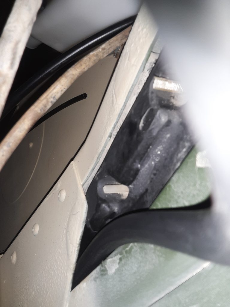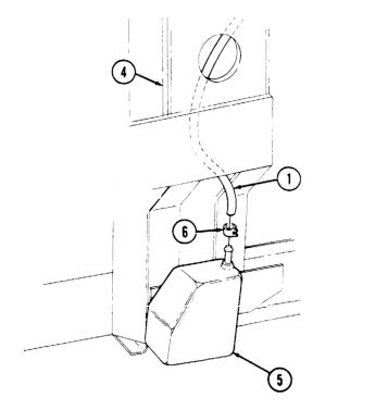
The above figure appears as if it is a straightforward task to insert the cup sensor to CDR vent hose (No. 1 in picture).
In fact, even the instructions, Sec. 12-13 (TM 9-2320-280-3) makes it appear that you simply have to “route vent line through “A” beam.”
It truly is not a simple task. Ours being a Marine unit seems to be lacking in most of the insulation. It did, however, have the insulation installed inside the “A” beam. We erroneously made the assumption that since our HMMWV was originally equipped with the fording system, it should be as simple as the manual indicated. We spent several hours trying to thread the hose from both the top and the bottom with no success. The hose would consistently stop around the halfway point.
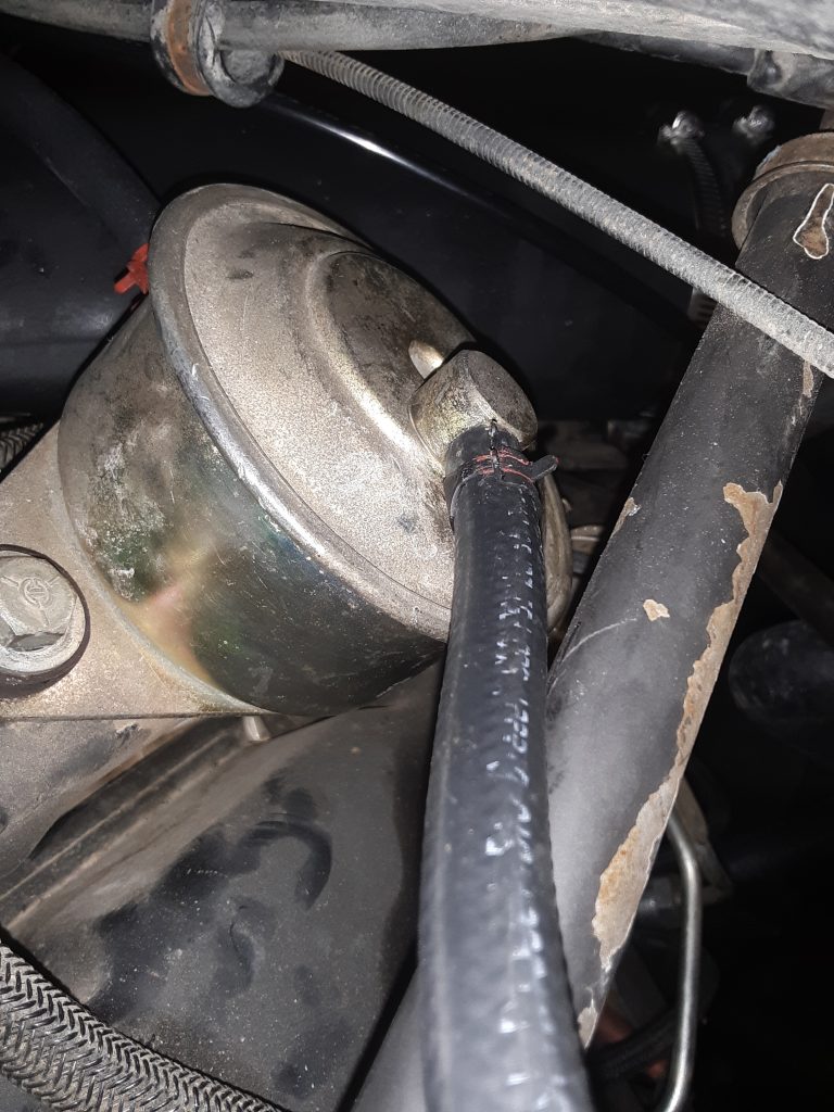
After running the lift up and down a number of times, we decided to see whether we could “fish” a piece of 3/8″ air brake tubing through the pillar. Although it took considerable effort, we were able to push the brake tubing completely through. We then connected the tubing to the hose with a 1/4″ hose barb and attempted pulling the hose through. That method failed on several tries.
We were ultimately successful using pure silicone (silicone gel for waterproofing / rubber boots, etc., not RTV) to lube the end of the hose and about half way up. The hose easily slid through. We suspect that there was just too much friction where the hose was somewhat pressed against the insulation.
Being that we have a crate of circa 1960 Dow Corning military surplus silicone, there was no cost. However, in the event you aren’t oversupplied with silicone gel, we strongly suspect that tire bead lubricant or even dishwashing soap would also serve as well.