Install Supplemental Armor on Splash Shields

A HMMWV radiator, as well as the cooler, are rather expensive. Although the splash shields do offer some protection from rocks and debris thrown from the front wheel, they are probably limited to offering protection against little more than water.

Plastic tends to break down over time and exposure to elements. Although our side shields appeared serviceable, we opted to install supplemental armor to provide additional protection.

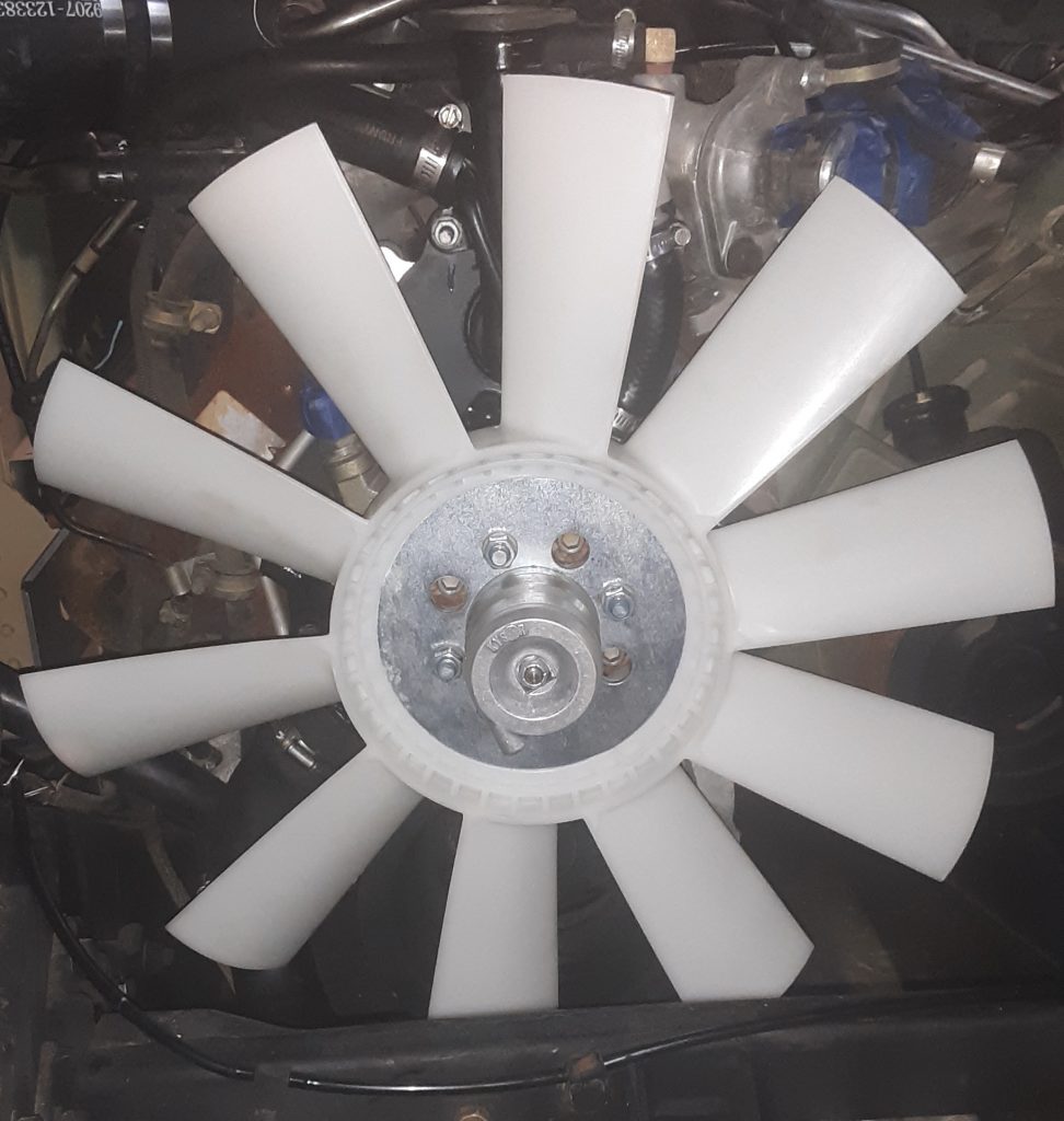
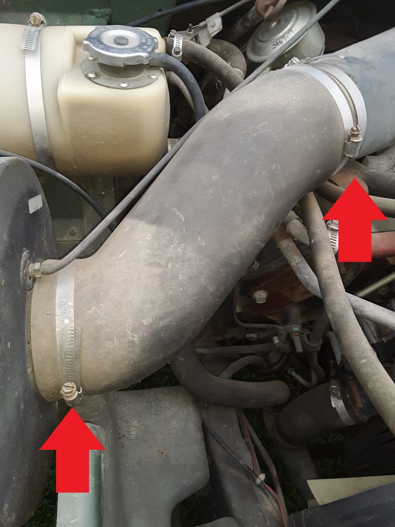
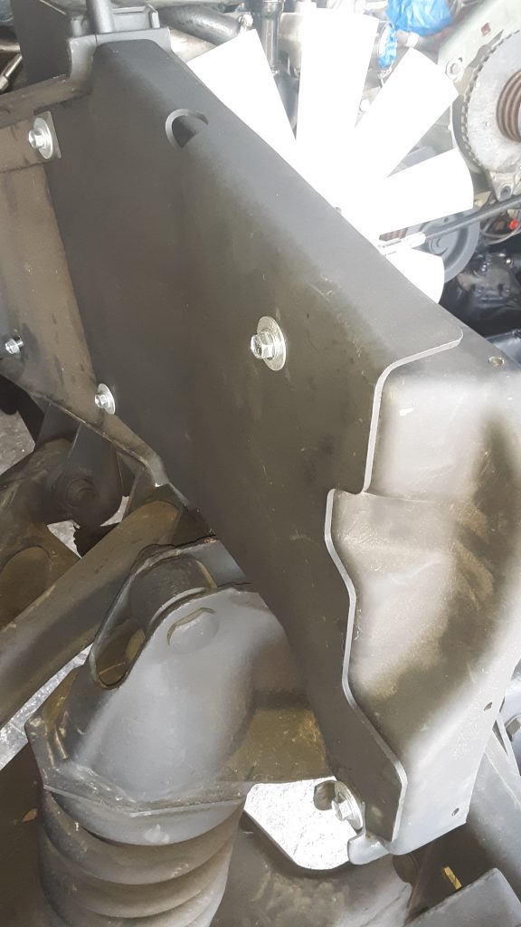
The picture below shows the RH side supplemental armor 2510-01-189-9744 [2510011899744] installed over the side shield.

There are two additional side shields available for each side. The standard (or basic) radiator shield for the RH side is 2510-01-185-7946 [2510011857946]. The supplemental armor is a little over twice as thick, and is called out as “armor plate.” The basic plate appears to be manufactured from mild steel.

Supplemental armor for the LH side is 9515-01-189-9728 [9515011899728], whereas the basic is 2510-01-185-3107 [2510011853107].

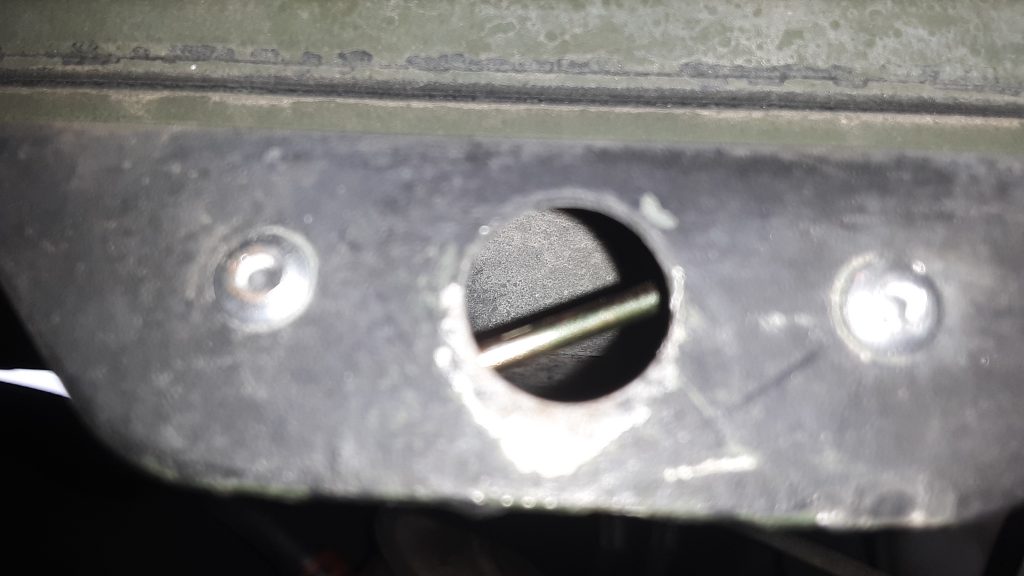
We also updated and improved the fasteners attaching the supplemental armor to the splash shields.

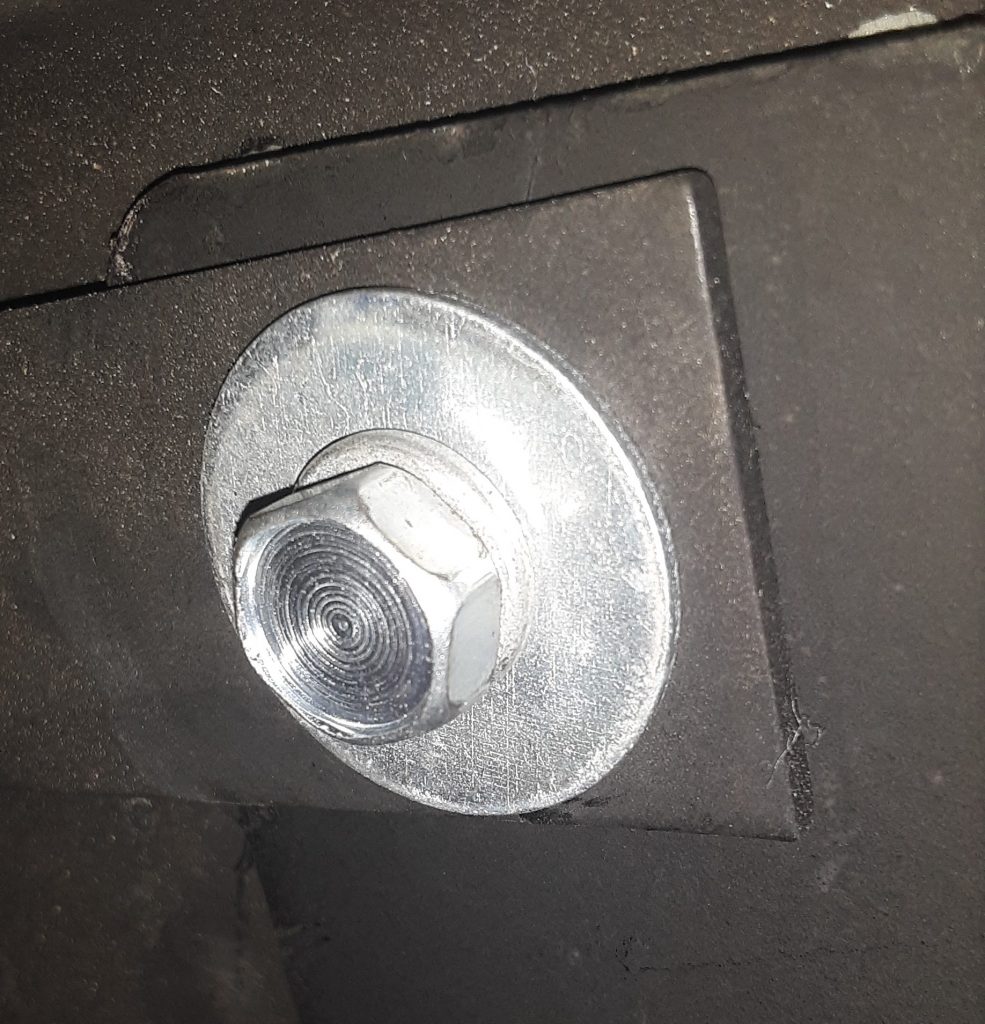
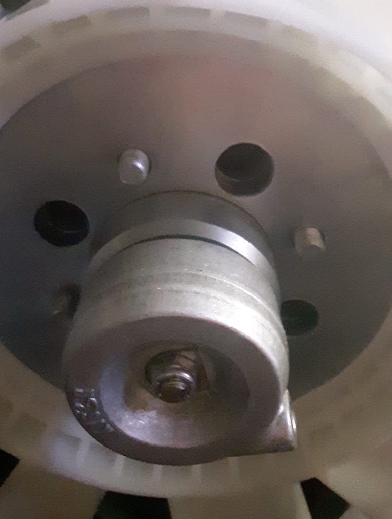
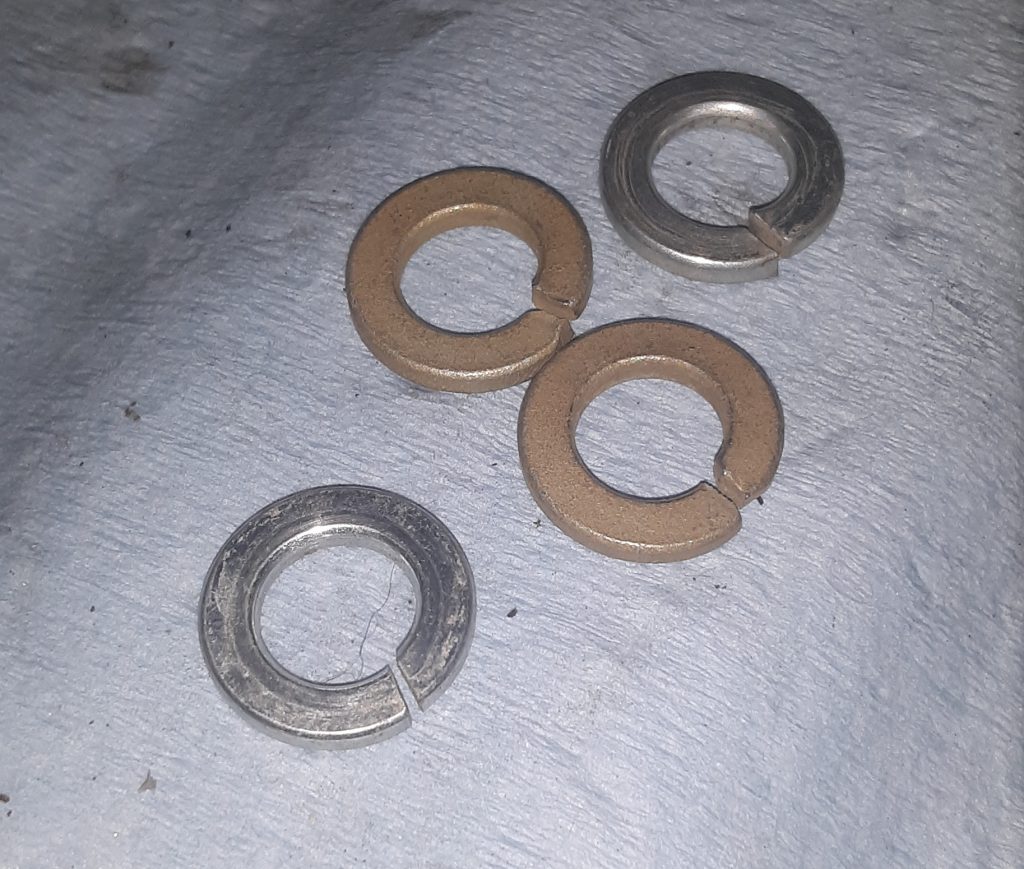
In the picture above, we did utilize the 5/16-18 x 1″ self tapping screw 5305-01-253-2993 [5305012532993] called out for attachment to the air lift mount. However, the TM calls out for a 5/16″ washer over a 3/8″ washer. We instead chose to use a 5/16″ lockwasher and a 5/16 x 1 1/8″ fender washer. In our opinion this offers an esthetic improvement as well as ensuring that the load is evenly distributed. We are unsure as to why this was not done instead of stacking two different size washers. Regardless, our substitution is appropriate.

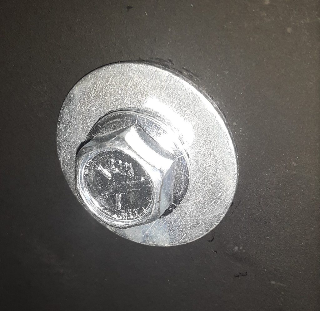
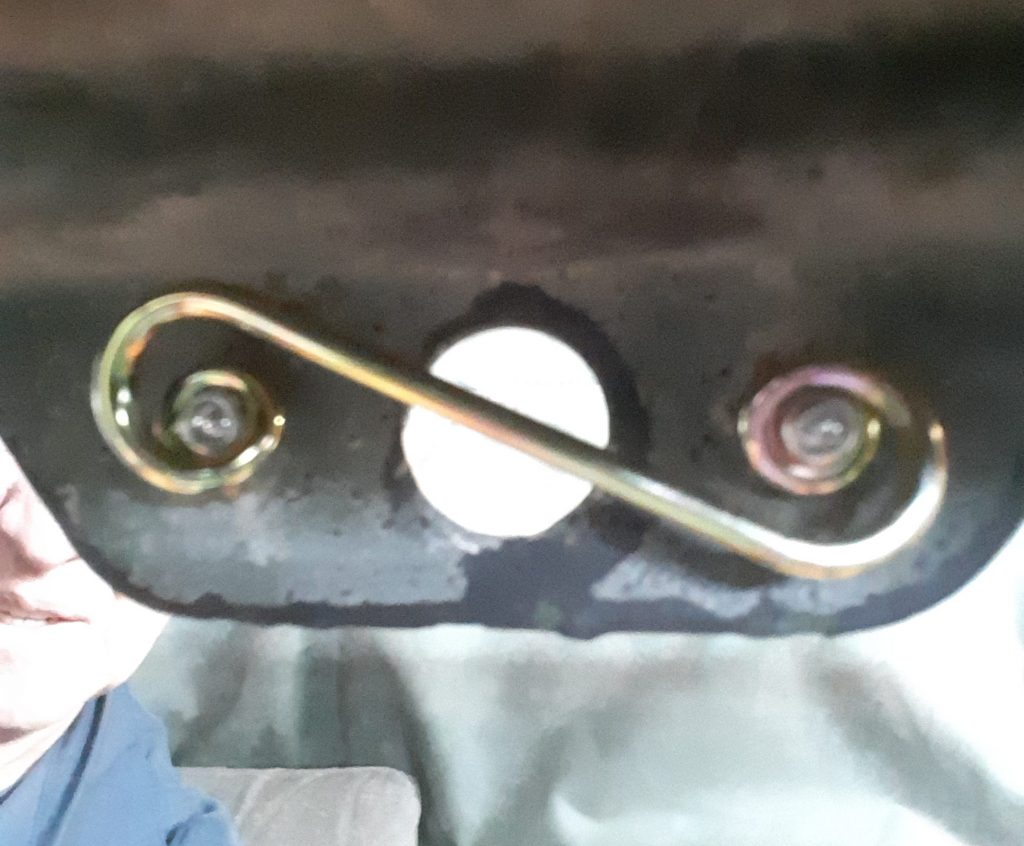
On the other positions that did not call for a self tapping screw, we substituted 5/16-18 x 1″ “Wiz” bolts and nuts (also known as serrated flange) in place of the regular bolts called out for in the TM. Because of the serrated flanges, these act to some degree as a lock washer, and the flanged head helps distribute load on the inner side of the splash shield. Also, again we used 5/16 x 1 1/8″ fender washers in place of the stacked washers called out.

Hose Clamps: Standard v. Liner

There are two primary types of “open” hose clamps. The two pictured above are SAE Size 72, which we determined is the commercial equivalent of clamp 4730-00-359-9487 [4730003599487].

On the right is the standard hose clamp. On the left is what is referred to as a “liner” hose clamp. The Red Arrow points to a shield that protects the hose from extruding through the “rack” portion of the hose clamp. Liner clamps are often called “military clamps,” but in fact, the liner is designed for clamping softer materials such as silicone hoses.

This size clamp is called out to tighten the 90 degree hose used to connect to the fording stack extension 2510-01-198-0333 [2510011980333] and to the air cleaner. (See Figure 398, Item 31).

Of interest, the standard hose clamp in Size 72 worked perfectly for the fording tube application, however the “liner” clamp was too small. In fact, the liner clamp was manufactured by Breeze, a company that is a supplier of hose clamps to the military.

Install Fan Clutch Pressure Line & Quick Disconnect

In an earlier post, we discussed interchange for the quick connector used on the fan clutch. Pictured below is the commercial equivalent of 4730-00-900-3296 [4730009003296] (Figure 178, Item 23), which is simply a 1/8″ x 1/8″ NPT nipple.

Although there are varying opinions on pipe dopes v. teflon tape, we prefer to use Rectorseal #5. It does come second only to anti-sieze at managing to make a mess, but we have successfully used this material for decades without encountering leaks.

Pictured below is the nipple and the quick disconnect discussed in the earlier posting. This is essentially one half of what is shown as Item 7 in Figure 178, and has been assembled to the fan clutch.

Below is the quick disconnect connected together along with hose 4720-01-189-0853 [4720011890853]. Note we have applied Rectorseal to all pipe threads.

Installation of Engine Cooling Fan

The fan used for either 6.2 or the 6.5 NA on the v-belt application is4140-01-211-8403 [4140012118403]. As discussed in this post, the quality and materials appear to be comparable to OEM. The fan itself centers on the diameter of the fan clutch. We had to dress the inside of the fan in order to install it. We do not feel this to be a flaw, but rather precise hand-fitting of the fan to the fan clutch.

The lock washers taken off of the fan appeared to have not retained its spring-like characteristics. We believe they used Grade 5 or less washers on installation. We replaced those washers with Grade 8 (the gold ones) to ensure locking capacity. (Of note, we also used Blue Loctite as an extra safety measure).

The silver lock washers were removed from the vehicle, the gold Grade 8 ones were used to replace them. Note: there are four lock washers required, only two of each were photographed as examples.
Picture of fan assembled to fan clutch.

Fan Clutch Installation

Having disassembled, inspected and repaired the fan clutch in a prior post, we install the clutch to the water pump (of which we discussed interchanges).

Torquing fan clutch to water pump bolts. Note use of aluminum tubing to stop rotation of fan assembly during torquing.

We were unable to easily locate the torque specifications for the fasteners. We referred to Alma Bolt Company & Prime Fasteners’ torque specifications for Grade 5 and Grade 8 bolts. Being that the fasteners on our powerplant were socket head (allen bolt), this is generally an indication of a Grade 8 fastener. According to Alma Bolt’s chart, a 3/8″ Grade 8 has a specified torque of 44 ft. lbs. for a plain bolt, and 33 ft. lbs. for a plated (or wet) bolt.

We set our torque wrench to 32 ft. lbs. and after applying Red Loctite to each fastener, evenly tightened down the fan clutch. After subsequent review, we note that TM 9-2320-280-20-2 specifies 45 lb-ft (page 3-135 Change 3 at c.1.). This is within the specifications provided in the Alma Bolt chart, as the TM does not specify use of loctite which lubricates the thread causing a lower torque reading to equal the same “tightness” as a higher torque with dry threads.

Install Engine Cover “Dzus” Clips

To replace the quarter turn fastener springs 5325-00-449-3001 [5325004493001] (Item 5 above), drill out the existing rivets 5320-00-083-5009 [5320000835009] (Item 6) with a 1/8″ drill bit.

These parts can be substituted as follows: First, the quarter turn spring can be substituted with Dzus or generic quarter turn fastener springs with the dimensions of spring height to latching surface .150″ to .175″ and measurements of 1-3/8″ eye to eye. Second, the rivets are simply 1/8″ diameter x 5/16″ length.

1/8″ rivets, Dzus-style fastener spring, and twist lock fastener 5325-01-191-7555 [5325011917555]

Install the springs using a “pop-rivet” gun as shown in the following pictures.

Upgrade/Interchange Heater Hose Clamps

As in previous posts, we have identified hose clamp sizes and their commercial interchange numbers. For the heater hoses, we have confirmed that SAE 10 is the correct size. Above are Breeze brand clamps, and Breeze has a history of manufacturing hose clamps for military use.

SAE Size 10 hose clamps installed on manifold to heater hose pipe.

Proper Transfer Case Fluid

As we discussed in an earlier post, Dexron III is what was called for in the Transfer Case, and use of Dexron VI has led to parts failure. As discussed, our research indicates that GM continues to recommend use of Manual Transmission and Transfer Case Fluid 88861800 for the transfer case.

As the picture indicates, this fluid is also marketed as AC Delco 10-4033. We used a Lincoln suction gun to fill the 242 transfer case. We had previously drained the transfer case to ensure no contaminants were present, and used just about 2 1/2 quarts to bring the fluid to the proper level.

Although we have identified fluids being marketed as “recommended for” Dexron III applications, we chose to use GM’s recommendation as we did not want to risk loss of a transfer case. However, we will likely use a “recommended for” Dexron III (H) fluid when we fill the transmission, and bleed out the cooler and winch.

Fording: Notch for Fuel Tank Vent Hose

Hose is Figure 398, Item 30. (The Corbin clamp is not on the vent tube at time of photo)

The arrow in the photo above indicates the position where the vent hose leading from the fuel tank vent line filter 2910-01-210-5872 [2910012105872] (behind the surge tank) is to be placed for clearance when the hood is closed. Note a Corbin style clamp 4730-00-954-1251 [4730009541251] needs to be placed on the hose ends both where the hose attaches to the tube and to the filter.

The callout for this hose is for an 11″ length of CPR104420-2 (replaceable with 3/8″ air brake tubing, such as Eaton Synflex®). We instead replaced this with 1/4″ SAE J30R9 hose (which we consider a modern and equal substitute for RB1450-1-4IDX1-20D).

Our reasoning for using hose instead of tubing is based on a couple factors: First, it is called out as RB1450-1-4IDx1-20D (or equivalent) to connect the fuel tank vent line to the fuel vent line filter (See Figure 18, Item 6). We are of the opinion the hose leaving the vent line filter should be the same as the hose entering the filter, and that indication of tubing may be an error in the TM. Second, use of air brake tubing essentially requires a heat gun to soften the tubing enough to slide over the tube on the stack and bead on the filter itself. Although this can be accomplished, should field repairs be necessary, it essentially requires cutting the tubing, where the hose can be easily removed by loosening the Corbin clamps.

Note: the drawing indicating the vent line hose appears to be the same as the hose entering the vent, and does not appear to be tubing. Although this may be based simply on the artist, we are of the opinion that the hose leaving the vent should be the same as the hose entering the vent.

We note the installation instructions for the DWF kit also indicates the CPR104420-2. See http://www.hummerknowledgebase.com/driving/dwf.html (at Image 3), where is specifically calls out an 11″ length. (We do, however, note this document is extremely dated, as it calls out for use of Dexron II at Image 5). Dexron II was long ago deprecated: In 1993, GM released new Dexron-III fluid (GM Spec GM6417M and later GMN10055). As noted above, we believe the J30R9 hose is made from material superior to what was available during original engineering of the HMMWV. and stand by our recommendation to instead use J30R9 hose.

Although we have no way of knowing at this time, there may have been a UV (sun) resistance issue where the engineers preferred the air brake tubing over the hose for that reason. It may well be that the CPR104420-2 tubing has a greater resistance to breakdown that the RB1450-1-4IDx1-20D hose. However, we are around 30-some years since the original design, and materials have changed. We will monitor the J30R9 hose to determine if it exhibits any undesirable weathering characteristics.

Interchange: Air Filter Hose Clamps to SAE Size

Arrows indicating locations of three hose clamps 4730-01-189-0871

Based on the call-out from the parts manual, the three hose clamps indicated below are 4730-01-189-0871 [4730011890871] or manufacturer number H68SS. Upon our research, these part numbers cross over to an SAE 68 hose clamp. Unfortunately, while size 68 clamps can be located, they are not generally commercially available. The standard (and readily available) sizes are either SAE 64 or SAE 72. We ordered both.

As it turned out (and we will post a picture later), SAE 64 is the perfect size for these three locations. We have noted that the specifications almost always call out a hose clamp considerably longer than necessary, and often leaving too much of a “tail” to grab debris, bend, and cut hands. (See photo below).

M998 Air Cleaner hose clamp showing excessive “tail” when called out part used

This hose clamp was unmodified and as received from the military. Based on what we could tell, this was a SAE 68 hose clamp.

We ordered the SAE 72 hose clamps to interchange for the clamps called out 4730-00-359-9487 [4730003599487] for use on the fording elbow 4720-01-194-5338 [4720011945338]. Although we have not yet installed these clamps, we predict they will have a considerable tail. However, those hose clamps are (for the most part) not quite as visible. On visual inspection, it appears that the SAE 68 (and possibly SAE 64) clamps may also be appropriate at that location. We will update should this information be found incorrect.