In several earlier posts, here and here, we discussed a suitable substitute for Armstrong Hose RB1450-1-4IDX1-20D. We stand by our opinion that 1/4″ silicone hose is appropriate for the vent hose from the front hubs to the tubing.
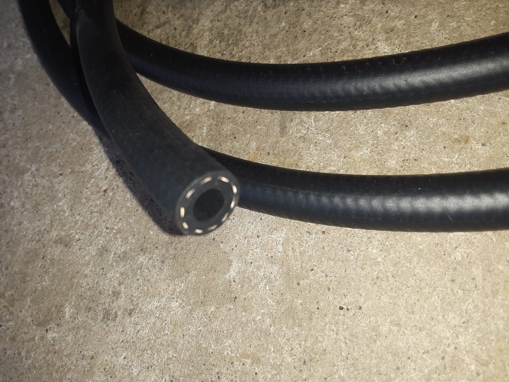
We received and installed the SAE J30R9 hose (fuel injection hose) for the underhood Deep Water Fording (DWF) applications of the fording valve 4820-01-192-8030 [4820011928030] to CDR valve 4820-01-192-7678 [4820011927678] and the sensor cup 2540-01-192-4502 [2540011924502] to CDR valve.
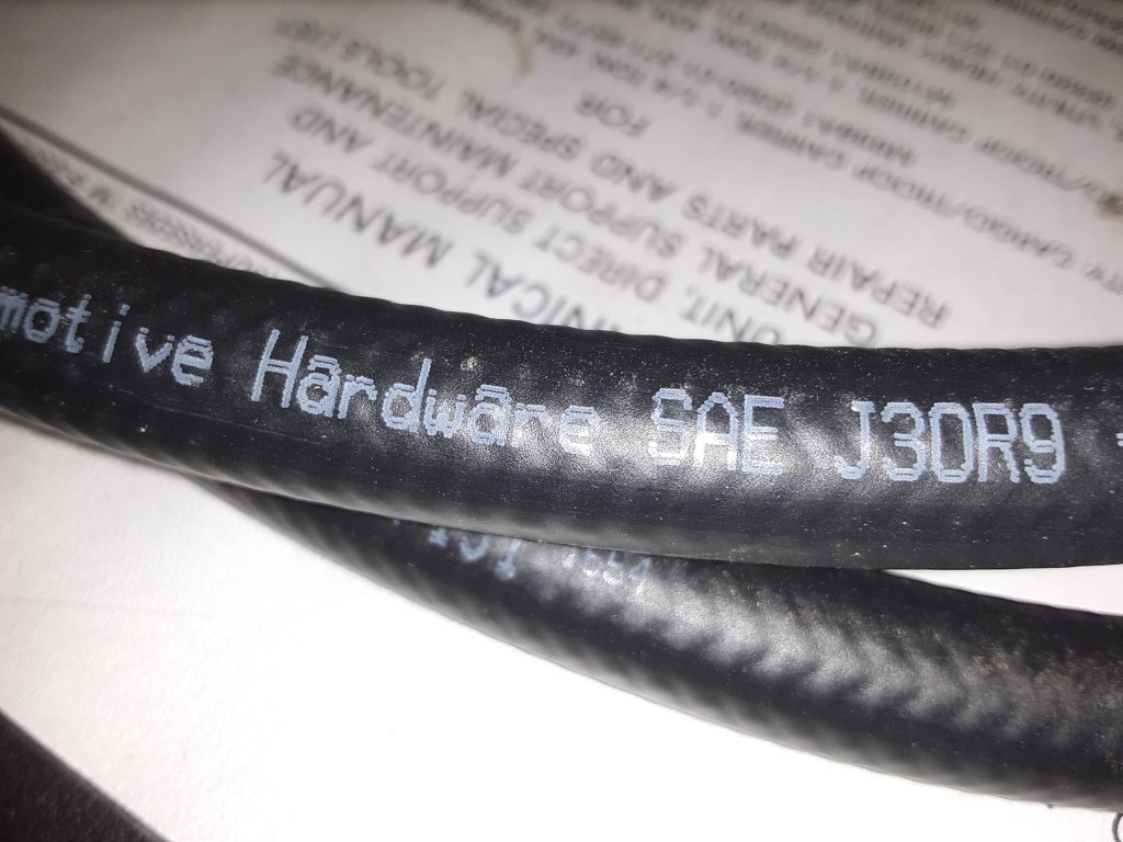
Pictures below are of the J30R9 hose utilized:
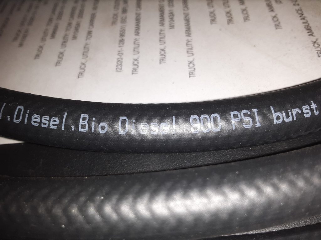
As noted in the earlier posts, this hose is rated at 100 p.s.i. operating pressure, and bursting pressure of 900 p.s.i. We feel this is more than adequate for venting purposes, and appears to be made out of more modern material that is specifically rated for diesel and bio-diesel (as well as other fuels).
SAE J30R9 hose labeled for use with Diesel and Bio Diesel
As a further note, we will be reviewing whether we also wish to replace the general fuel lines with this hose, as we noted during our review of the M998 that it was using SAE J30R7 hose. As we noted in an earlier post, we were denied sale of J30R7 hose to California ostensibly because J30R7 hose has too high of a fuel permeation rate.
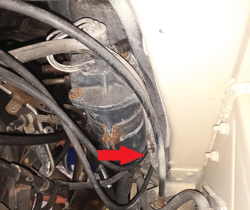
Arrow points to location of fording valve on firewall (located adjacent and behind fuel filter)
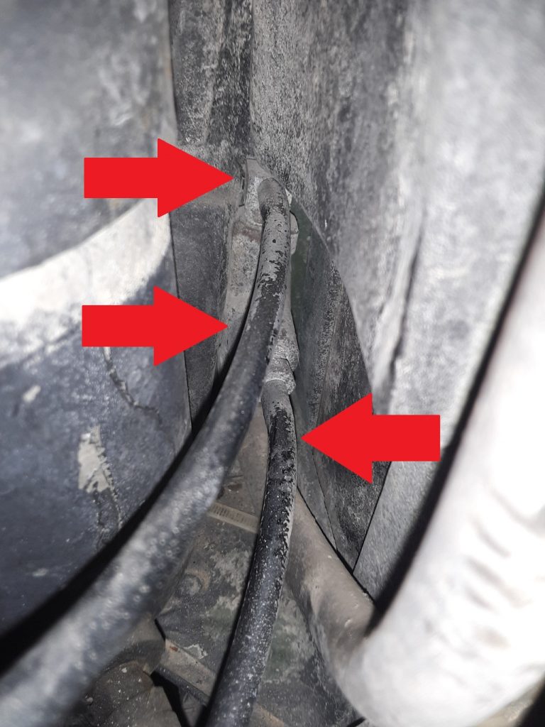
As we are replacing the 30-some year old hose and tubing with new, we need to access the fording valve to remove and replace the hoses. The below picture shows the hoses attached to the fording valve.
Picture of fording valve with arrows pointing at the three hoses attached to fittings.
Both the upper and the middle tubings are called out as P/N CPR104420-1, while the bottom hose is called out as P/N RB1450-1-4IDX1-20D. As discussed in an earlier post, the CPR104420-1 can be interchanged with 1/4″ air brake tubing, such as Eaton Synflex®. Similarly, we have determined that although not a direct interchange, we could use either 1/4″ silicone hose or 1/4″ SAE J30R9 hose (fuel injection hose). For this application, even though the silicone hose has a much higher temperature rating, we had concern about abrasion on the hose so we substituted the J30R9 hose instead of the silicone. We do however, believe that the silicone hose would be more than acceptable as a substitute under most circumstances.
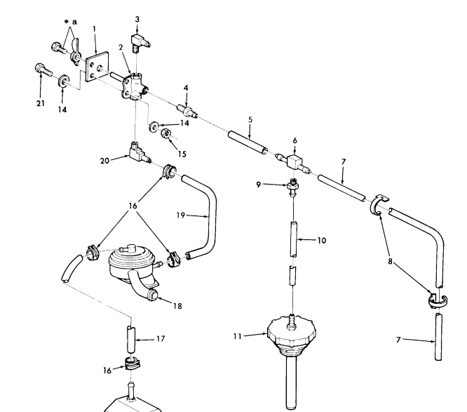
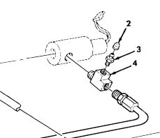
The parts manual shows an exploded view of the hoses and tubing that connect to the fording valve.
Excerpt from Figure 399
As shown above, the fording valve 4820-01-192-8030 [4820011928030] (Item 2) has three hoses connected to it. The lower hose goes to the lower fitting on the DWF (Deep Water Fording) CDR valve. The middle tubing goes to a line running across the cowling and tees into the vent line from the power steering pump cap. Although this is considered a special cap for DWF applications 2590-01-192-4425 [2590011924425], it is simply a standard power steering cap with a 1/8″ nipple adapter screwed into a hole in the center of the cap.
We have diagrammed the middle hose connection (Item 7) and fording valve top connection (Item 3). to view the diagram, please refer to this updated post.
In previous posts, we have indicated that we have substituted RB1450-1-41DX1-20D hose with 1/4″ silicone hose for the vent lines leading from the front hubs to the vent system.
This same hose is indicated for use on vent lines and in the fording kit. We have found that this interchanges to Eaton Weatherhead H10104.
UPDATE (12/29/2018): Apparently AC Delco 32102 (SAE J30R7) is not legal in California. We were denied sale both by Amazon and Ebay vendors. At this time it appears its illegality is that it has too high of a fuel permeation rate relative to other hose ratings (despite the fact we are using the hose for venting, not fuel). We have ordered SAE J30R9 hose (fuel injection hose) in place of the AC Delco 32102.
J30R9 hose is still quite not identical in specification to the RB1450-1-41DX1-20D hose, as it is is rated to a maximum operating pressure of 100 p.s.i. (compared to the 350 p.s.i. of the Eaton H10104), and a burst pressure of 900 p.s.i. Regardless, for underhood and venting purposes, J30R9 hose will be superior to the J30R7 hose.
The temperature rating of J30R9 is -31°F to 275°F (intermittent to 302°F); which is superior to either the J30R7 or the H10104, although the cold temperature limit has been slightly decreased from -40 F to -37 F.
************************* older information below**************************
We have ordered AC Delco 32102 (the 25′ length of SAE J30R7 1/4″ hose) as a potentially less expensive, but just as serviceable replacement. Our concern is not heat (as silicone has considerably greater working temperature range), but more concern about potential abrasion issues.
This hose is intended for Fuel Line PCV/EEC, and is apparently repackaged Gates hose. Intended for low pressure (50 p.s.i.), this should suffice for venting purposes as well as be able to handle underhood heat. (rated -40 F to 257 F).
It is rated considerably lower than Eaton H10104, which has a pressure rating of 350 p.s.i, but a slightly lower rating of -40 F to 212 F.
Although Dexron III is called out as the proper fluid for the transfer case, GM has deprecated Dexron III and replaced it with Dexron VI. ( a synthetic transmission fluid originally thought to be completely backward compatible for all uses).
Why not just use Dexron VI?
Dexron VI has been found unsatisfactory for use in some transfer cases, and has led to or caused hardware failures. Our research indicates that GM owns the rights to the specifications and licensing of manufacture of Dexron III. In 2005, GM released the new 6 speed transmission and Dexron VI as a synthetic fluid approved for it. In 2006, GM discontinued licensing manufacture of Dexron III fluid. This means that no one can technically make Dexron III compliant fluid because it existed only at GM’s permission.
Although Dexron VI was originally assumed to be backwards compatible, it was soon discovered that both manual transmissions and transfer cases were failing at an unexpected rate. Because of this, GM released a “new” fluid for manual transmissions and transfer cases that is essentially a fluid manufactured to GM Dexron III specification.
As the majority of HMMWVs in use (at least by the public) predate the 2005 change, it is safe to assume that Dexron VI would not be a suitable substitute. As late as 2007, GM released a PI warning against the use of Dexron VI in 2007 and prior vehicles. #PIP3836B expressly states: DO NOT use Dexron VI in place of the manual transmission fluid in any manual transmissions or transfer cases as a failure may result.
What should be used instead?
Our research indicates GM continues to recommend Manual Transmission Fluid 88861800 in place of Dexron III. From what we can determine, this fluid is merely relabled Dexron III, albeit potentially with some additives.
We have also seen recommendation of GM Fluid 88900402 (Auto Trak II Transfer Case Fluid) as a suitable replacement for Dexron III in transfer cases. We have not, however, been able to find a GM recommendation of this fluid over 88861800.
We have also been advised that Amsoil makes a Dexron III replacement for use in transfer cases, but have no further information. I would love to hear others’ comments on fluid substitution.
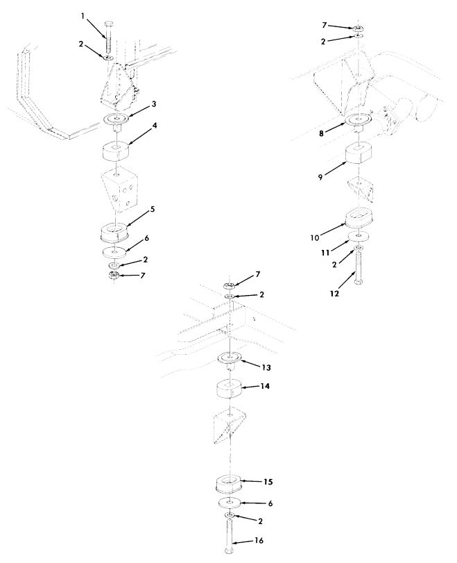
Body Mounts. The parts manual shows three different “spacers” or more accurately, washers (Fig. 196. Items 6 & 11), used underneath the lower body mount cushions.
Of these, there are several NSNs. For the Front LH side, it is 5310-01-476-9321 [5310014769321], which also carries P/N 12339248-3. The Front RH and the rear use 5310-01-252-7285 [5310012527285] (12339248-2). The intermediate mounts (the ones in the middle) call out 5365-01-214-4987 [5365012144987 5583215].
Other than the front left hand side (the most difficult mount to deal with because it bottoms onto the frame and can only handle a maximum diameter washer), we can find no reason for use of different washers at the different locations.
First, it is unclear what purpose these washers serve. We speculate that it is either to 1) spread the load across the metal portion of the lower mount; or 2) (in event of catastrophic mount failure), it would prevent the body from separating from the frame. There could also be some other reason we simply don’t know, but we have never seen washers used in this way for automotive purposes.
To be clear, we are not discussing the spacers used between the body and the upper mount to provide armor clearance on later versions.
After ordering all of the proper washers, two were on backorder status and we were only able to obtain two washers used for the front LH application, 12339248-3. (We like to keep extra parts in stock). This washer measured out at 5/8″ x 2 3/4″ x .250″.
Having only the LH washer/spacers, they measured at 5/8″ x 2 3/4″ x .250. The front LH definitely has a clearance issue, as that is the single mount with a “bucket” welded over the frame.
Comparing this washer to the lower months, it still covers the bulk of the metal on the largest mount, the intermediate mount 5342-01-186-7236 [5342011867236] (12339247-3).
Upon determining that the smaller diameter washer appears to also work in the other positions, and being unable to timely source the washers/spacers called out for the right front, intermediate and rear positions, we determined that a washer of 3″ diameter will both fit and service properly.
We will use the extra front LH washer in the front RH location, and ordered four 5/8″ x 3″ x .250″ washers to be plasma-cut by my brother, David Grundman. As the washer 5310-01-476-9321 [5310014769321] we do have appears to be galvanized, we will be powder coating the plasma-cut washers for corrosion protection.
We will update this posting should we find any issues with using the washers in the positions as described above. If anyone has any insight as to why different washers are utilized, we would appreciate hearing from you.
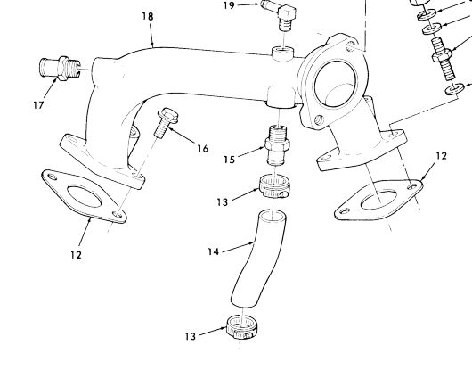
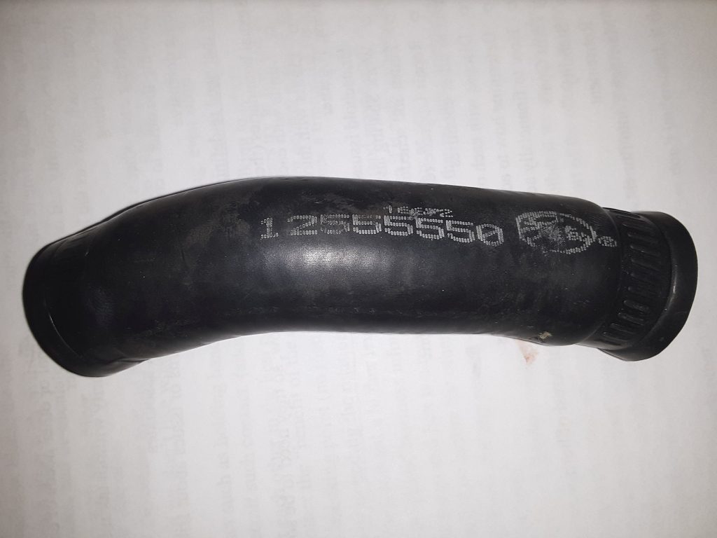
One of the often overlooked segment of the cooling system is the coolant bypass hose. (Fig. 30, Item 14)
The Parts Manual does not provide a NSN for this hose, but it does specify the manufacturer number as 23500084 for the 6.2 and 6.5 NA.
On our 6.5 NA, the hose itself is marked as Gates 12555550.
We were unable to locate this part number under any cross-reference. The TM specifies the hose can be made from P/N 4377 at a 5″ length for the 6.2/6.5 NA. We were similarly unable to identify or cross-reference this part number.
As the TM indicates the hose is identical for the 6.2 and the 6.5 NA, we researched the hose for the 6.2 diesel and identified three GM part numbers: AC Delco 30124, AC Delco 30127 and GM 88909065. Each of these part numbers return as 5/8″ coolant hose.
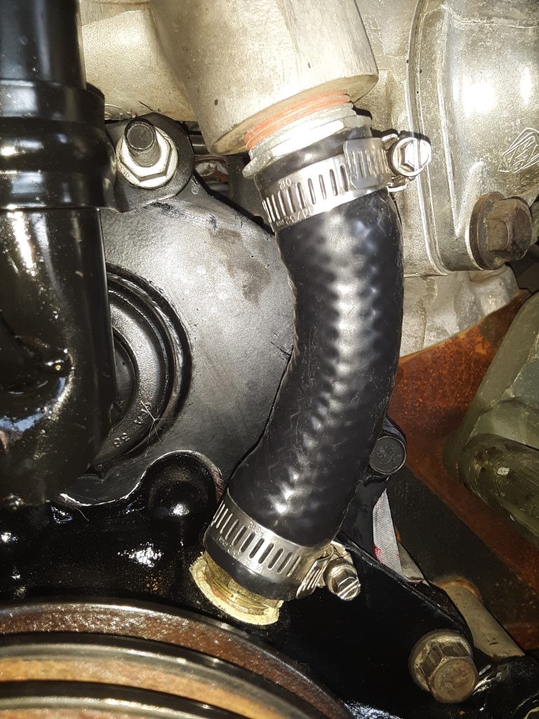
Update: Regardless of the call-out in the TM and cross-reference, the hose on our 6.5 NA was 3/4″ not 5/8″.
We note that there are references found on the internet that people have unsuccessfully identified this as 3/4″ hose. These experiences indicate that the hose appears to fit, but leaks, and was subsequently identified that the application calls for 5/8″ hose instead of 3/4″ hose. As an upgrade, and to prevent future maintenance issues we have acquired 5/8″ silicone coolant hose. (in black, to maintain original appearances). We re-ordered 3/4″ black silicone coolant hose, as our 6.5 NA application requires 3/4″ not 5/8″ This hose is often used on agricultural and industrial applications and sometimes carries a higher pressure rating. (200 p.s.i. vs. 60 p.s.i.) Additionally, the jacketing on the silicone hoses seem to degrade slower than the EPDM hoses, and seem somewhat more resistant to abrasion. (foreign material being blown into the hose from the cooling fan).
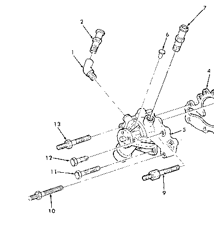
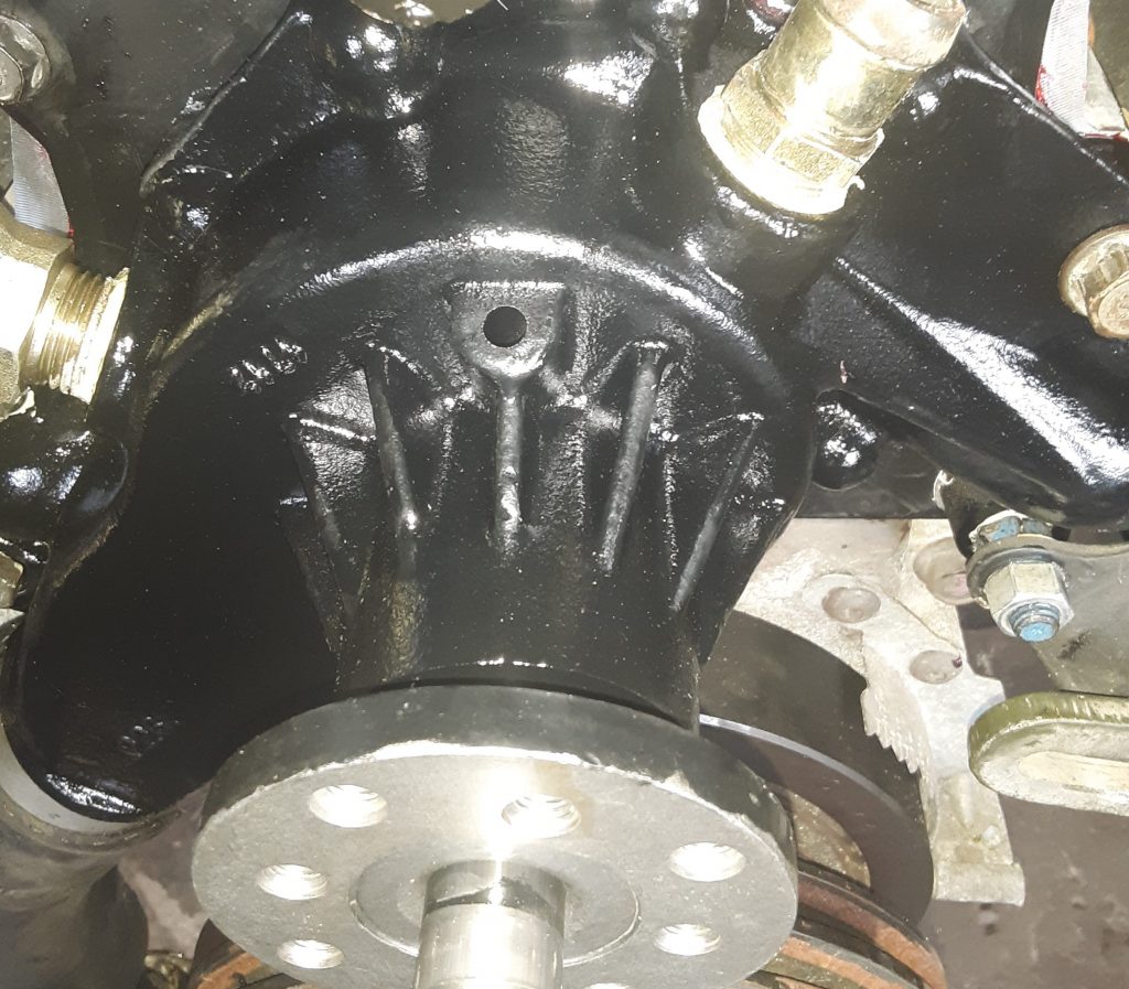
According to the Parts Manual, a rivet is to be installed into the upper weep hole of the water pump. (Fig 31, Item 6).
This rivet is 5320-01-218-0721 [5320012180721], and is described as RIVET, SOLID 1/4 X 1/2. This rivet is visible on the water pump we removed from the 6.5 NA. (between the coolant bypass fitting and the heater hose fitting).
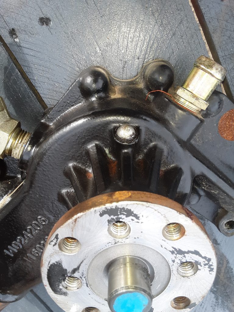
Factory installed rivet in upper weep hole
Our replacement water pump, as installed, did not have this rivet.
We removed the rivet from the original water pump by prying it out with a screwdriver. It appears that the rivet was held in (or glued in) using Loctite 518 or similar. (“grape jelly”). We noted that the 518 had not set up, either because the engine had not run enough to heat up, or it was simply the wrong material to use.
After removing the rivet, we installed it in our water pump using Permatex No. 2, which does harden up with air, but remains pliable. Although No. 2 has falled into disfavor over the years in place of materials such as RTV and pressure hardening sealants such as Loctite 518, we still find No. 2 suitable (and in some cases, superior) to modern sealants, and especially in this application.
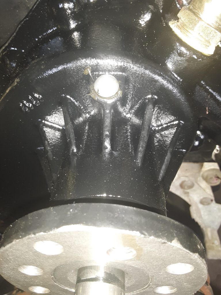
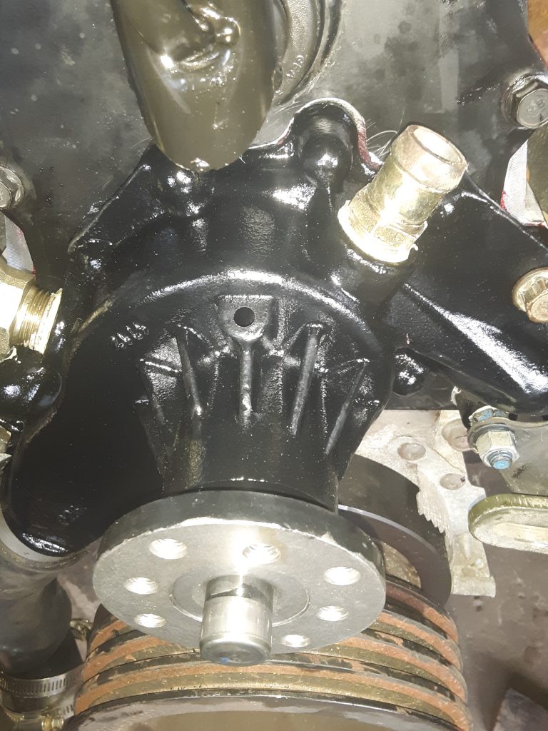
Rivet installed into water pump per Fig. 31, Item 6.
We are unsure of the precise reason as to why the call out requires a rivet to be installed into the water pump. And this may explain the price discrepancy between interchange water pumps and OEM water pumps. In our opinion, moving the rivet from the old pump to the new one (or even buying a new rivet) makes for a considerably less expensive replacement.
I consulted with Tim Grundman of Big Dawg Diesel Worx, LLC, and he informed me that he had never seen a weep hole plugged with a rivet on any industrial or agricultural applications. And although this particular powerplant had not come from a vehicle with the fording upgrades, we speculate that the purpose of plugging the upper weep hole is to prevent contaminants from entering the weep hole and affecting the outer seal on the water pump bearing.
According to our research, this base water pump was used on a number of applications other than the 6.2 and 6.5 diesels. Likely there may have been an application where the water pump mounted upside down from this application, allowing the weep hole to show leakage regardless of position.
Further, it may be that under fording applications, plugging this hole prevents waterborne foreign material from lodging into the front of the water pump and aggravating seal damage.
Regardless of the reason, replacement or purchase and installation of a rivet will keep this water pump as factory designed.
As discussed in an earlier posting, we needed to replace the water pump on our 1038, and chose to use an AC Delco 252-611 as a replacement. Once the water pump arrived, we first inspected the external housing to determine that it was dimensionally the same as the damaged pump, and found that it was virtually identical to 23500085.
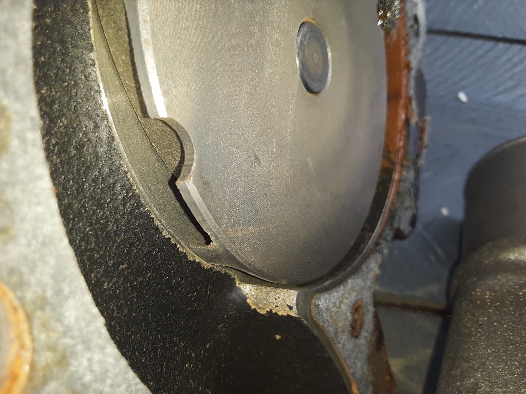
Second, as discussed in the earlier posting, we needed to confirm that the rotation of the pump was correct. (V-belt applications use a rotor that rotates in the same direction as the engine, while serpentine belt drives require an impeller designed to work in the opposite direction).
6.5 NA Original Water Pump P/N 23500085 (v-belt application)
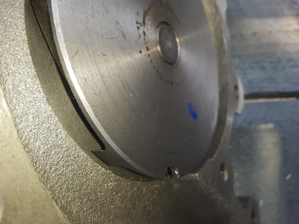
Upon visual confirmation, the impeller vanes are the same.
Replacement Water Pump AC Delco 252-611 (v-belt application)
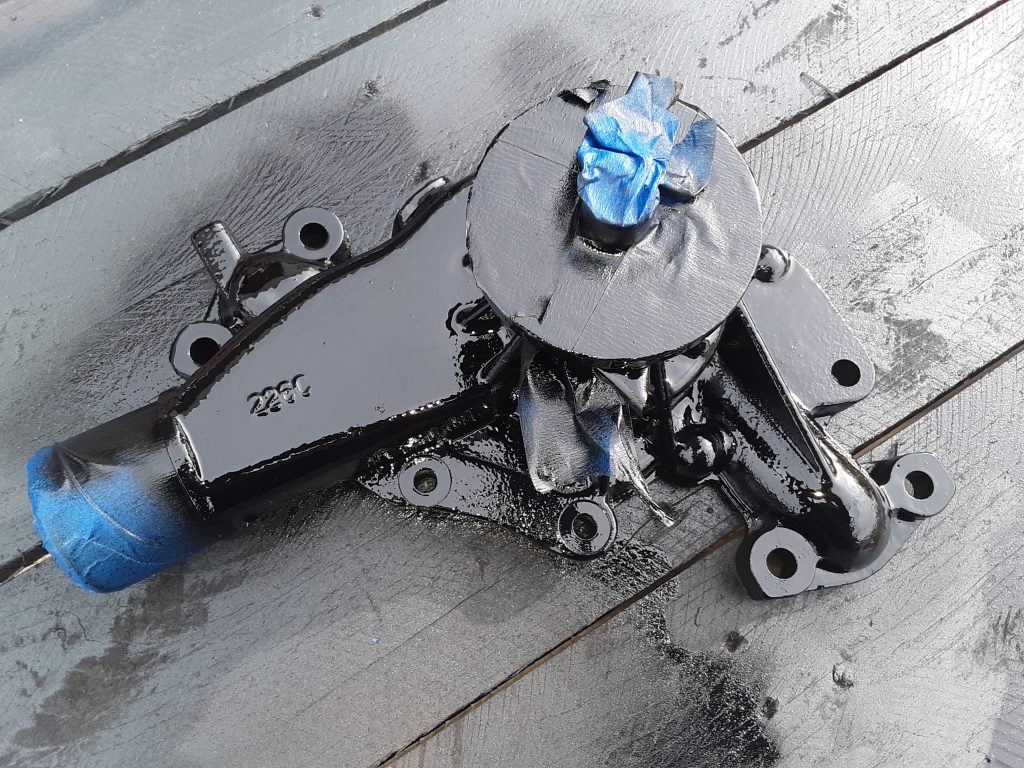
After confirming the AC Delco 252-611 was a proper replacement, we painted the water pump with a glossy engine enamel to match the original pump. In painting a water pump be sure to not paint the face where the pulley mounts, the bearing (as paint can damage the seal), the ports where the fittings go (to ensure proper sealing), and the area where the lower radiator hose mounts to the pump.
Note masking to prevent paint on areas that should not be painted. After removing the masking tape, we were ready to install the pump.
As a note, we installed all bolts holding the timing gear cover and the water pump to the timing gear cover with blue Loctite. As there are seven bolts holding the water pump installed from the inside of the timing gear cover, it is extremely important to use Loctite and torque to specifications. Should one of these bolts loosen or fall out, they fall directly into the timing gears.
Additionally, there are five bolts installed from the outside that are tapped into the water jacket. It is important to re-apply sealant on these threads to ensure engine coolant does not leak on the threads. We used Rectorseal #5, but other products will also suffice.
UPDATE: As we reviewed the drop-shipping invoice, the water pump is billed out as a GM 88926125. This application shows at least for civilian 1990 6.2L, and also corresponds with Airtex AW5008 indicated in a prior post.
During transit, one of the cooling fan blades on our powertrain sustained damage. While it would likely still be serviceable under some situations, we investigated, and ultimately replaced the part with one of Chinese manufacture.
The fan used in our unit is the same for either the 6.2 or the 6.5 NA on the v-belt application 4140-01-211-8403 [4140012118403]. We spoke with representatives of IvyWay Truck Parts https://www.ivywaychina.com/ and acquired a manufactured-in-China fan to test and review.
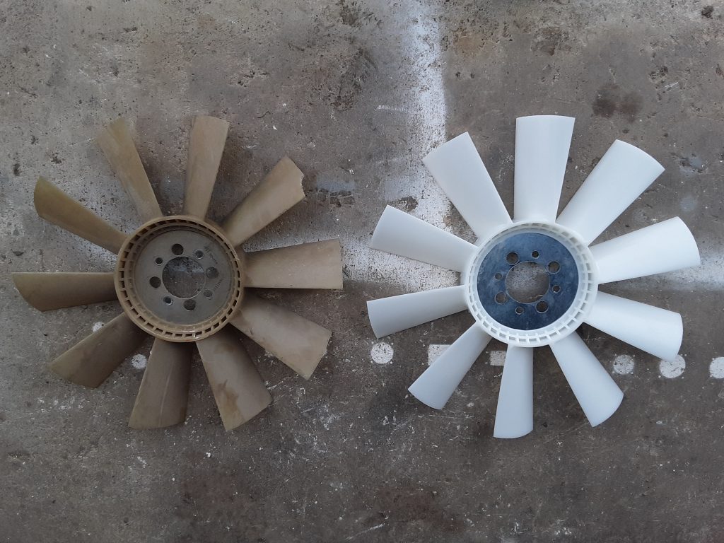
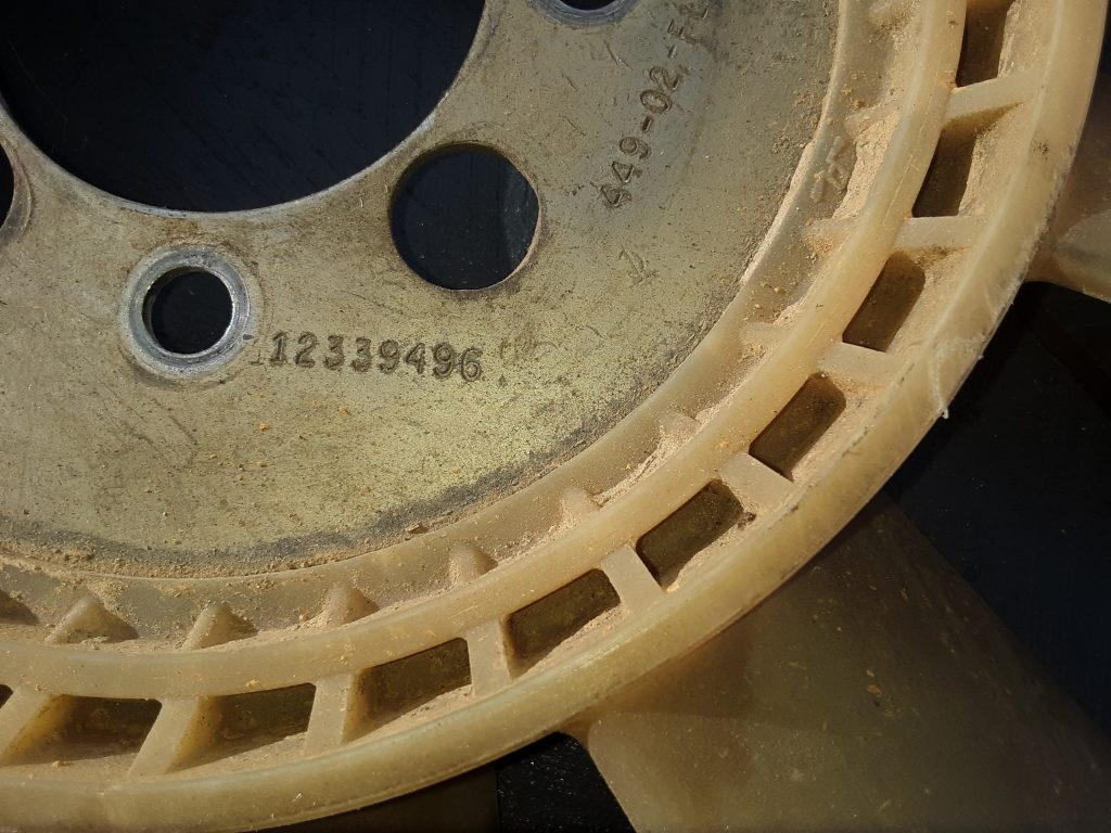
The original fan is on the left, and the Ivyway fan is on the right. (note chip missing out of blade on original fan). We went over the Ivyway fan with a caliper and could not find any difference between the two other than the Ivyway did not carry the AM General part number:
And that small gussets molded into the base of each blade. (which we determined was an improvement over the original). [Picture yet to be uploaded]
The price difference between the Ivyway and the AM General fan is a factor of about 4 times. Additionally, we feel that the gusset molded into the blades is an improvement and should add additional strength.
We will run the Ivyway fan in our Project: M1038 to determine how well it holds up and report later if we note any issues. We do feel comfortable, however, that the quality is likely on par with the original part, especially since most plastics manfacturing is done overseas anyway. (e.g. carbon fiber bike frames, YETI coolers, etc.)
At this time, we are of the opinion this HMMWV part manufactured in China is as good, or possibly superior, to the OEM part.
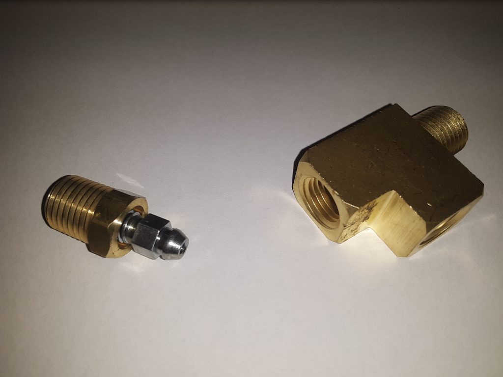
One relatively expensive and difficult to locate fitting is the bleeder valve assembly (Fig. 178, Item 3 & 4) on the line charging the fan clutch. This assembly consists of a TEE, PIPE 4730-01-473-8047 [4730014738047], and a bleeder screw 4820-01-473-3580 [4820014733580].
The purpose of this bleeder is to ensure all air is removed from the hose leading to the fan clutch 2930-01-168-7870 [2930011687870]. Although we have since applications where the hose threads directly into the solenoid, this can be considered an upgrade to those situations. Overall, it is generally better practice to purge air from the system at the highest point. Even if you bleed the system using the quick-coupler near the fan clutch as a bleed point, any air remaining in the hoses or fittings from the solenoid to the fan clutch may still likely travel to the highest point.
The pipe tee itself appears to be a common 1/4″ NPT Street Tee, however the perpendicular hole is instead threaded to accept a bleeder screw.
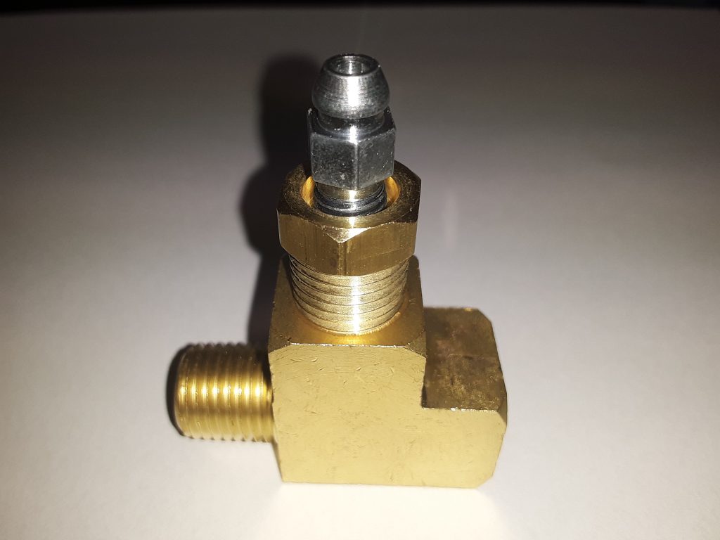
Our solution is to actually use a regular brass 1/4″ Street Tee with a specialized 1/4″ fitting incorporating a bleeder screw.
1/8″ NPT bleeder screw adapters are extremely common and easily located on eBay and Amazon. However, we wanted to avoid using a 1/8″ to 1/4″ bushing. We were able to locate a 1/4″ NPT bleeder adapter, although it is not specifically marketed as 1/4″. The CTA Tools 1235 Brake Bleeder Screw Repair Kit, 3/8-Inches is actually a repair fitting intended for defective brake bleeders on calipers such as Brembo and others.
As the hydraulic pressure used in the fan system is only 100 to 150 p.s.i., we feel comfortable that fittings designed to handle brake fluid pressures (800 to 2000 p.s.i (applied pressure)) should be more than sufficient. In this application, we intend to machine the fittings so that the bleeder adapter sits as low in the fitting as possible, and will post pictures after machining.