In several earlier posts, here and here, we discussed a suitable substitute for Armstrong Hose RB1450-1-4IDX1-20D. We stand by our opinion that 1/4″ silicone hose is appropriate for the vent hose from the front hubs to the tubing.
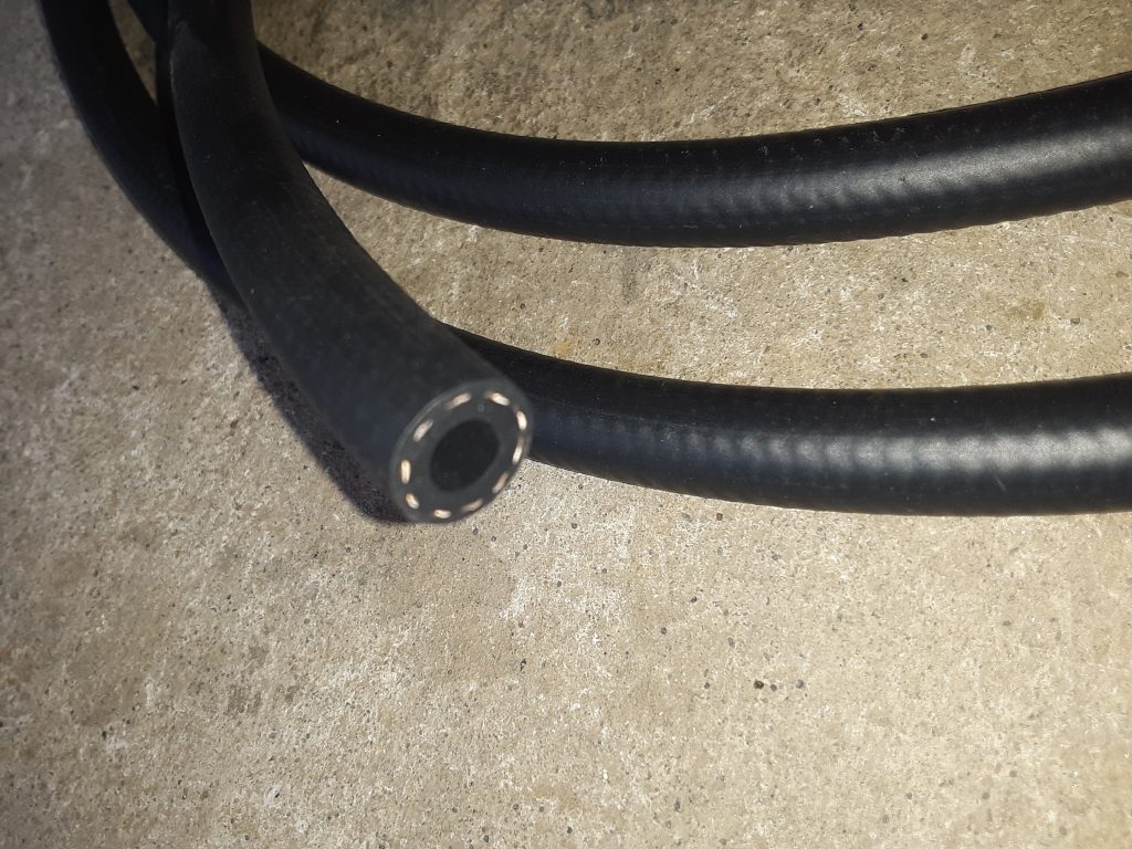
We received and installed the SAE J30R9 hose (fuel injection hose) for the underhood Deep Water Fording (DWF) applications of the fording valve 4820-01-192-8030 [4820011928030] to CDR valve 4820-01-192-7678 [4820011927678] and the sensor cup 2540-01-192-4502 [2540011924502] to CDR valve.
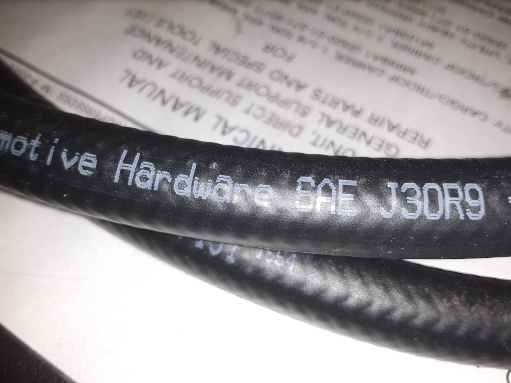
Pictures below are of the J30R9 hose utilized:
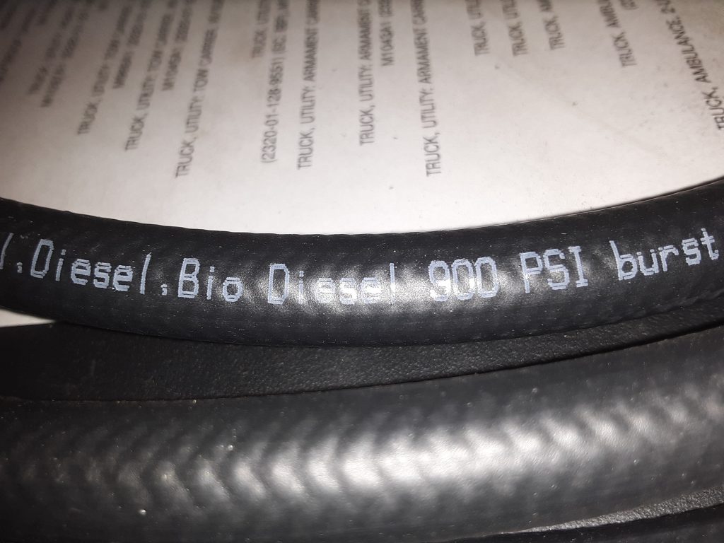
As noted in the earlier posts, this hose is rated at 100 p.s.i. operating pressure, and bursting pressure of 900 p.s.i. We feel this is more than adequate for venting purposes, and appears to be made out of more modern material that is specifically rated for diesel and bio-diesel (as well as other fuels).
SAE J30R9 hose labeled for use with Diesel and Bio Diesel
As a further note, we will be reviewing whether we also wish to replace the general fuel lines with this hose, as we noted during our review of the M998 that it was using SAE J30R7 hose. As we noted in an earlier post, we were denied sale of J30R7 hose to California ostensibly because J30R7 hose has too high of a fuel permeation rate.
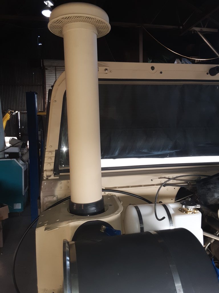
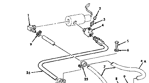
We obtained a complete fording intake stack from Alan Post. By complete, we mean the stack extension 2510-01-198-0333 [2510011980333], the clamps 5340-00-079-7837 [5340000797837], the vent tube 4710-01-209-6746 [4710012096746], and the windshield mount bracket 5340-01-238-9543 [5340012389543] with fasteners.
As you may notice, the rubber extends a little higher than normal at the base of the stack. We had ordered several 4 1/2″ silicone 90°s, to see how they would work. As it turns out, the actual AM General part is slightly less than 90°. Use of the silicone 90° required cutting the end that connects to the air cleaner at a slight “off-angle,” as did the portion that connects to the stack. We have instead ordered the correct fitting to replace this, however use of the silicone 90° would definitely be adequate and completely serviceable.
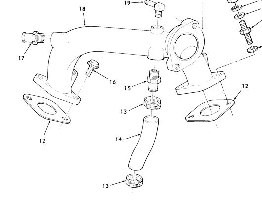
One of the often overlooked segment of the cooling system is the coolant bypass hose. (Fig. 30, Item 14)
The Parts Manual does not provide a NSN for this hose, but it does specify the manufacturer number as 23500084 for the 6.2 and 6.5 NA.
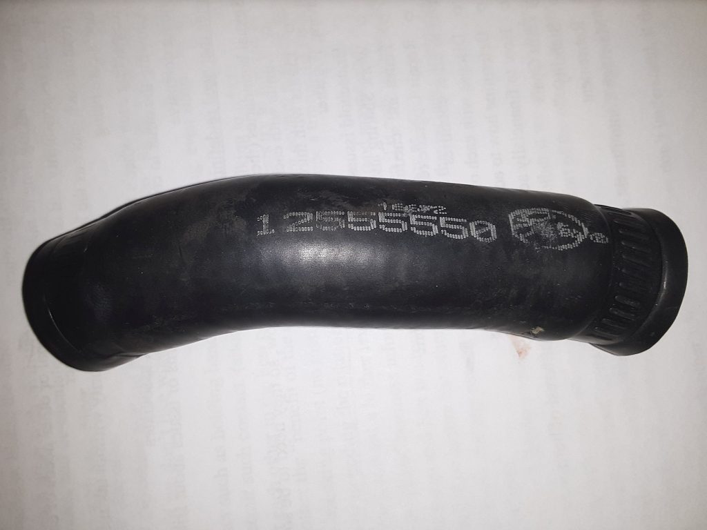
On our 6.5 NA, the hose itself is marked as Gates 12555550.
We were unable to locate this part number under any cross-reference. The TM specifies the hose can be made from P/N 4377 at a 5″ length for the 6.2/6.5 NA. We were similarly unable to identify or cross-reference this part number.
As the TM indicates the hose is identical for the 6.2 and the 6.5 NA, we researched the hose for the 6.2 diesel and identified three GM part numbers: AC Delco 30124, AC Delco 30127 and GM 88909065. Each of these part numbers return as 5/8″ coolant hose.
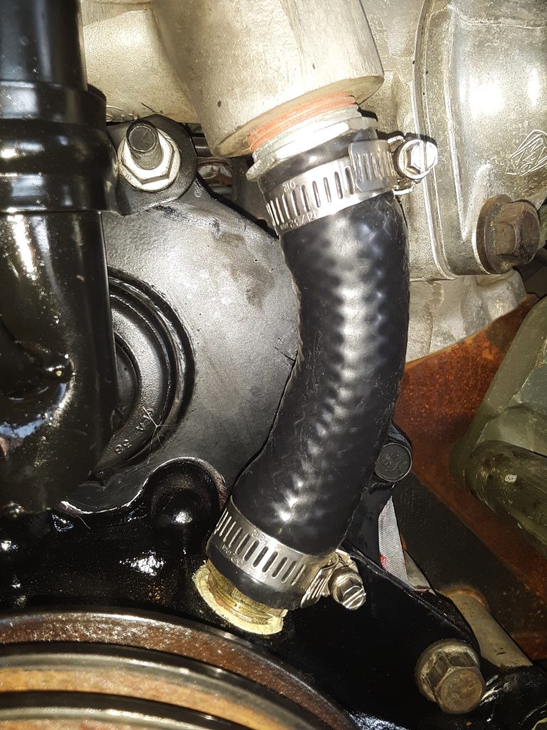
Update: Regardless of the call-out in the TM and cross-reference, the hose on our 6.5 NA was 3/4″ not 5/8″.
We note that there are references found on the internet that people have unsuccessfully identified this as 3/4″ hose. These experiences indicate that the hose appears to fit, but leaks, and was subsequently identified that the application calls for 5/8″ hose instead of 3/4″ hose. As an upgrade, and to prevent future maintenance issues we have acquired 5/8″ silicone coolant hose. (in black, to maintain original appearances). We re-ordered 3/4″ black silicone coolant hose, as our 6.5 NA application requires 3/4″ not 5/8″ This hose is often used on agricultural and industrial applications and sometimes carries a higher pressure rating. (200 p.s.i. vs. 60 p.s.i.) Additionally, the jacketing on the silicone hoses seem to degrade slower than the EPDM hoses, and seem somewhat more resistant to abrasion. (foreign material being blown into the hose from the cooling fan).
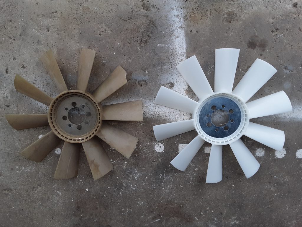
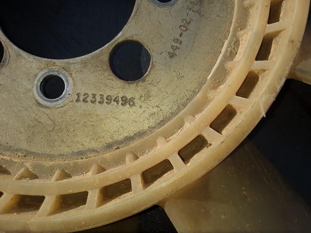
During transit, one of the cooling fan blades on our powertrain sustained damage. While it would likely still be serviceable under some situations, we investigated, and ultimately replaced the part with one of Chinese manufacture.
The fan used in our unit is the same for either the 6.2 or the 6.5 NA on the v-belt application 4140-01-211-8403 [4140012118403]. We spoke with representatives of IvyWay Truck Parts https://www.ivywaychina.com/ and acquired a manufactured-in-China fan to test and review.
The original fan is on the left, and the Ivyway fan is on the right. (note chip missing out of blade on original fan). We went over the Ivyway fan with a caliper and could not find any difference between the two other than the Ivyway did not carry the AM General part number:
And that small gussets molded into the base of each blade. (which we determined was an improvement over the original). [Picture yet to be uploaded]
The price difference between the Ivyway and the AM General fan is a factor of about 4 times. Additionally, we feel that the gusset molded into the blades is an improvement and should add additional strength.
We will run the Ivyway fan in our Project: M1038 to determine how well it holds up and report later if we note any issues. We do feel comfortable, however, that the quality is likely on par with the original part, especially since most plastics manfacturing is done overseas anyway. (e.g. carbon fiber bike frames, YETI coolers, etc.)
At this time, we are of the opinion this HMMWV part manufactured in China is as good, or possibly superior, to the OEM part.
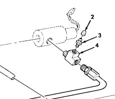
One relatively expensive and difficult to locate fitting is the bleeder valve assembly (Fig. 178, Item 3 & 4) on the line charging the fan clutch. This assembly consists of a TEE, PIPE 4730-01-473-8047 [4730014738047], and a bleeder screw 4820-01-473-3580 [4820014733580].
The purpose of this bleeder is to ensure all air is removed from the hose leading to the fan clutch 2930-01-168-7870 [2930011687870]. Although we have since applications where the hose threads directly into the solenoid, this can be considered an upgrade to those situations. Overall, it is generally better practice to purge air from the system at the highest point. Even if you bleed the system using the quick-coupler near the fan clutch as a bleed point, any air remaining in the hoses or fittings from the solenoid to the fan clutch may still likely travel to the highest point.
The pipe tee itself appears to be a common 1/4″ NPT Street Tee, however the perpendicular hole is instead threaded to accept a bleeder screw.
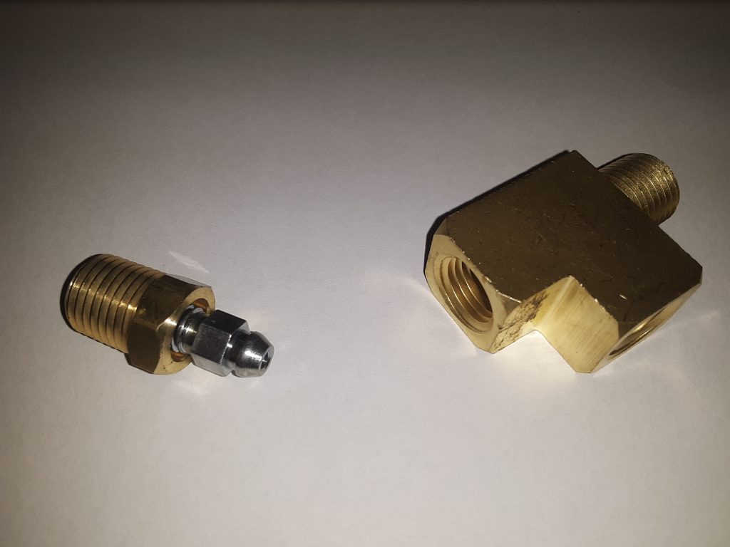
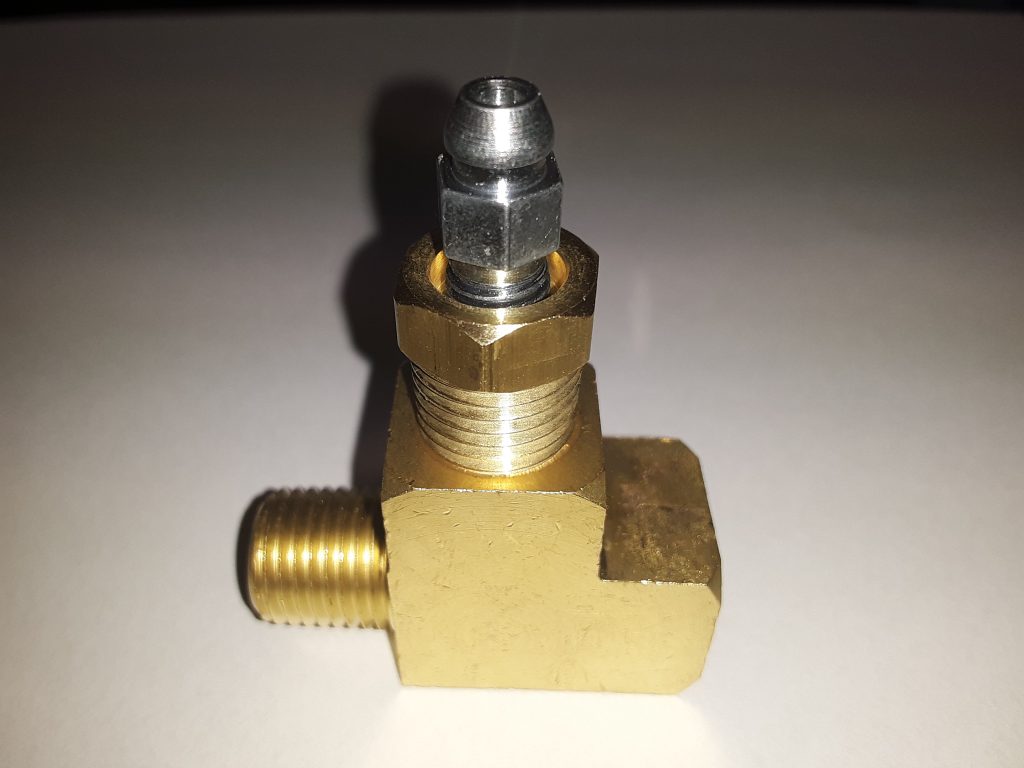
Our solution is to actually use a regular brass 1/4″ Street Tee with a specialized 1/4″ fitting incorporating a bleeder screw.
1/8″ NPT bleeder screw adapters are extremely common and easily located on eBay and Amazon. However, we wanted to avoid using a 1/8″ to 1/4″ bushing. We were able to locate a 1/4″ NPT bleeder adapter, although it is not specifically marketed as 1/4″. The CTA Tools 1235 Brake Bleeder Screw Repair Kit, 3/8-Inches is actually a repair fitting intended for defective brake bleeders on calipers such as Brembo and others.
As the hydraulic pressure used in the fan system is only 100 to 150 p.s.i., we feel comfortable that fittings designed to handle brake fluid pressures (800 to 2000 p.s.i (applied pressure)) should be more than sufficient. In this application, we intend to machine the fittings so that the bleeder adapter sits as low in the fitting as possible, and will post pictures after machining.
Determining what size hose is required to route to the cooler and the fan clutch solenoid is confusing based on the parts manual.
For example, the fitting from the return line from the cooler to the fan clutch solenoid (Fig. 178, Item 1) 4730-00-789-0951 [4730007890951] is designated as manufacturer p/n 110-03604 which is apparently an Eaton Aeroquip 90 degree brass fitting of 1/4 NPT x 5/16 hose barb.
However, the hose specified to go over the barb (Fig. 178, Item 7) is P/N 6490610019 which translates into AM General 5741209, which is assigned NSN 4720-01-186-2358 [4720011862358] and is also known as GM 6210M.
Per General Motors Corporation, the 6210M specification covers “…a 9.5 mm inside diameter hose made from textile reinforcement and synthetic rubber for use in hydraulic steering applications as a flexible connection between the power steering gear and the power steering pump or pump reservoir.”
The closest fraction to 9.5 mm is 3/8, which is exactly 9.5250 mm. Whereas 5/16 = 7.9375 mm. We checked the dimensions of other fittings called out for use with this hose (e.g., 4730-01-481-6278 [4730014816278] ). Its dimension is stated as “NOMINAL INSIDE DIAMETER HOSE ACCOMMODATED 0.290 INCHES 2ND END” or, slightly less than 5/16″.
We further found in the parts manual other references to P/N 6490610019, which gave an alternate AM General part number of 12338330, which is again defined as flexible hose (along with a suffix -X number) of 3/8″ diameter with applications ranging from Air Horn to CTIS (-7), transmission (-1. -2, -5), and power steering (-6, -9).
It seems axiomatic to use a 3/8″ hose with a 3/8″ barb fitting, not a 5/16″ barb fitting as the call out indicates. However, throughout the parts manual it systematically calls out for 5/16″ barb fittings.
We are of the opinion that using a 5/16″ barb with a 3/8″ hose is an error. The barb itself is 1.5875 mm smaller diameter than the hose, and that means that the hose would have to be tightened considerably just to contact the shank of the barb.
We inspected the old and damaged hose removed from the 1038. There were no markings, but it appears to be a 3/8″ hose. Further, 3/8″ power steering hose is considerably more readily available commercially (and at considerably lower cost) than the 5/16″ version.
We ordered and have on hand Gates 350010 Power Steering Return Hose (which is a S.A.E. J189 Power Steering Return Hose 3/8″ x 25′ bulk package).
We can find no valid reason for the mismatch between the sizes of the fittings and the hose called out in the parts manual.
We will update or change our findings regarding the discrepancy between the parts manual call out of 5/16″ barb fittings and the use of 3/8″ hose as we complete the hydraulic plumbing of the 1038.
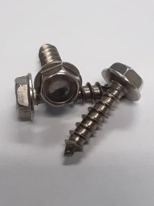
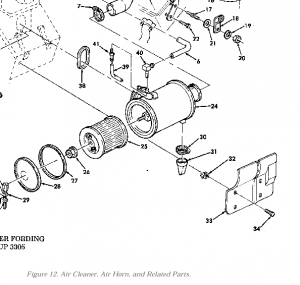
The screws attaching the air cleaner shield 2540-01-196-4726 [2540011964726] (Fig 12, Item 34) to the body in conjunction with shield, expansion 5340-01-208-8688 [5340012088688] are listed as SCREW,TAPPING #10-16 X 1/2 5305-00-058-1082 [5305000581082].
This can easily be upgraded with a stainless screw (Search “#10 X 3/4″ Stainless Indented Hex Washer Head Screw”) on Amazon or your favorite auction site.
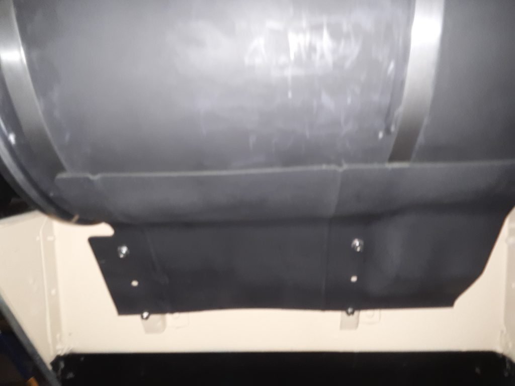
Note the four stainless screws holding the shield in place (at bottom of picture)
This same screw can be used as a substitute to mount the fuel tank filler neck, which specifically requires a 3/4″ length #10 5305-01-264-5874 [5305012645874] (Fig 199, Item 50).
NOTE: Although the call out for the expansion screw is for a 1/2″ length, there is adequate room to permit use of the 3/4″ length. Additionally, the requirement for 16 TPI isn’t relevant because it is essentially self-threading into nylon. The call out for the filler neck does require 12 TPI (because they thread into Tinnerman nuts), so purchase screws that meet this requirement and substitute for the 16 TPI thread. There is no reason to purchase different screws for each of these applications.
The 6.2 and 6.5 commonly will leak from the injector fuel return line hoses. (Fig. 11, Item 23). There is no NSN assigned to these hoses, rather they are cut to length from hose p/n 9439046. As these hoses age and dry out, they tend to crack and break, resulting in fuel leaks on the engine and onto the exhaust manifolds.
We installed new upgraded replacement hose sourced from Badger Diesel in Kenosha, Wisconsin. (262-859-2444). Unlike the original hose, the extremely small (and easily distorted) hose clamps 4730-00-150-6118 [4730001506118] are not required as the hose fastens securely to the fittings by itself..
Badger markets a complete kit to replace the return hoses as Badger Diesel 6265RLK. According to Badger, “This kit includes more than enough line to do the full job with 8″ of line per injector rather than the 3″ that the competition offers having only enough to barely do half the job. Thats 266% more line!” Badger further points out this hose is made in Germany, not China as is apparently their competitor’s hose.
In our opinion, this hose is a definite upgrade from the factory hose, and not having to use the extremely small and difficult-to-use hose clamps is a plus.
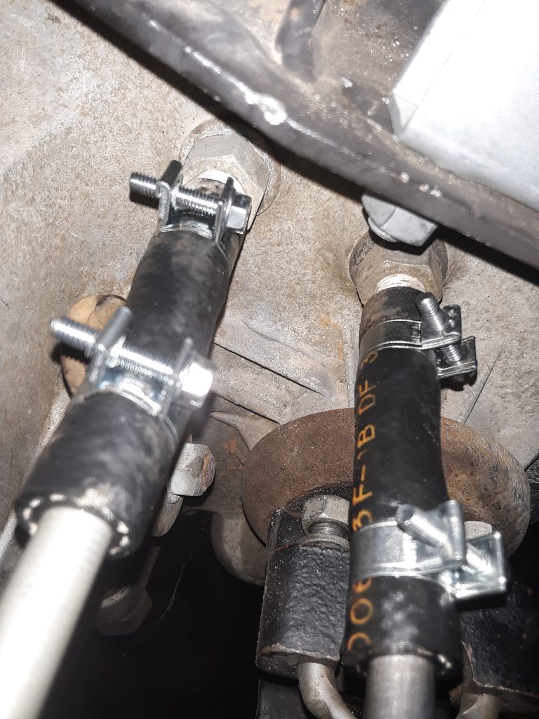
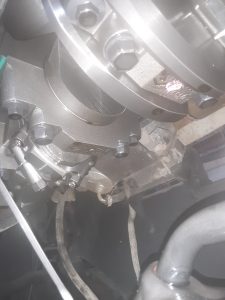
A common problem with standard hose clamps is that they will often tighten up unevenly, cock sideways, and require excessive torque to seal. Here, we have replaced the hose clamps on the transfer case cooling lines with fuel injection clamps (14-16mm range). While these generally cost considerably more than a standard hose clamp, they offer improved sealing and reliability. They can be bulk sourced at a number of online sites, often at a greatly reduced price.
The picture aboves shows where we replaced the original hose clamps 4730-01-118-8278 [4730011188278] with 14-16mm (9/16″-5/8″) fuel injection clamps. The original clamps were apparently installed at the factory from the top side of the frame prior to installing the body. We re-oriented the clamps so that they would be easier to adjust or remove & reinstall from under the vehicle.
These are still the original hoses that came with the powertrain. Although we had new hose to replace it with, we did remove and inspect the hoses. The hose itself remains “live” and showed no sign of cracking, so we retained the original hoses and installed the new clamps.
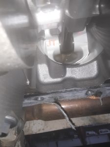
The engine oil pan was crushed during shipment, necessitating replacement. Whether that was the fault of the shipper or the seller, we don’t know. After finally locating a new replacement pan, the old one was removed. This engine does not look like it could have over 100 hours. Most likely, it appears that whatever HMMWV this powertrain came out of, it was likely a 6.2 that was upgraded to the 6.5NA and then sent for scrapping.
Internal view of 6.5NA showing virtually no wear or use. Picture showing extremely clean, extremely low hour engine internals.
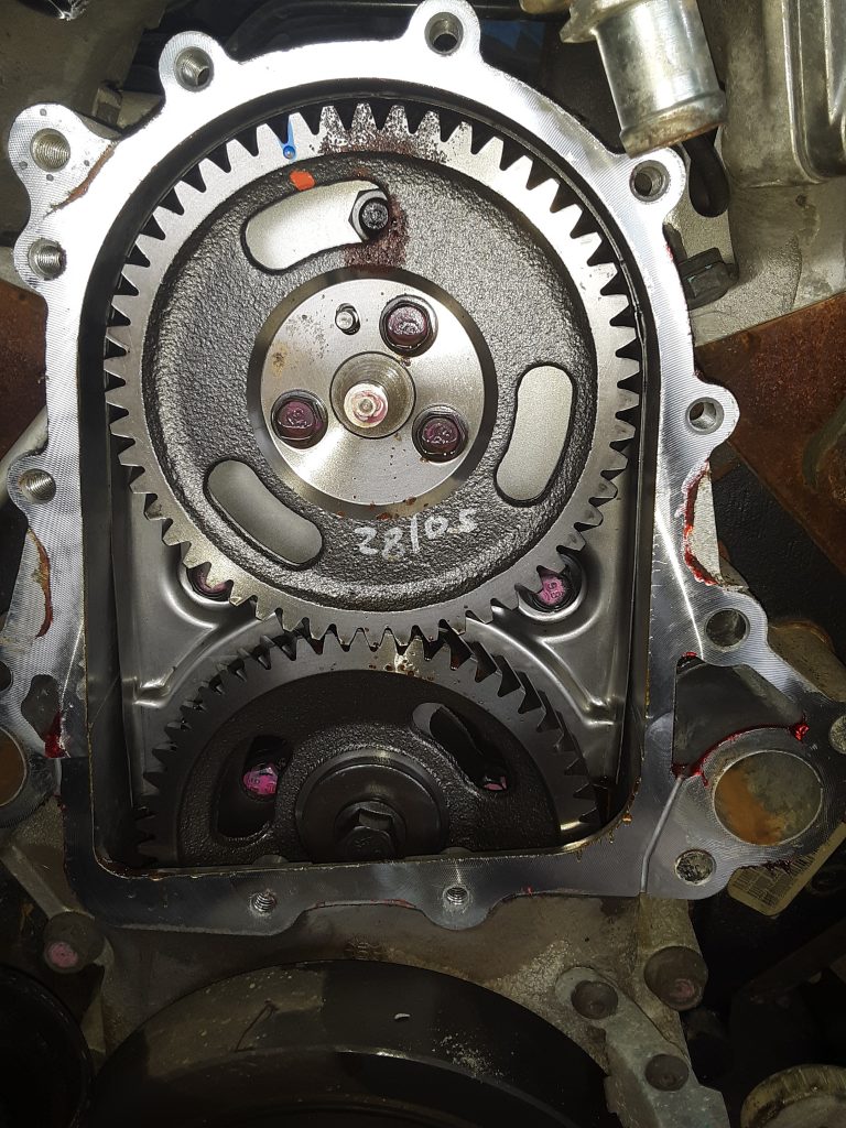
Update (Dec. 15, 2018): As we had to remove the timing cover to replace the water pump, we were afforded another view into the internals of the engine:
As visible, this is clearly a fresh engine. Not even the paint marks have discolored from oil and heat, and the Loctite 518 (or similar) had not been washed away. There is a slight amount of rust visible at the top of the upper timing gear caused by ambient air entering through the oil fill, but this should be considered normal, especially on an engine obtained from a de-mil.
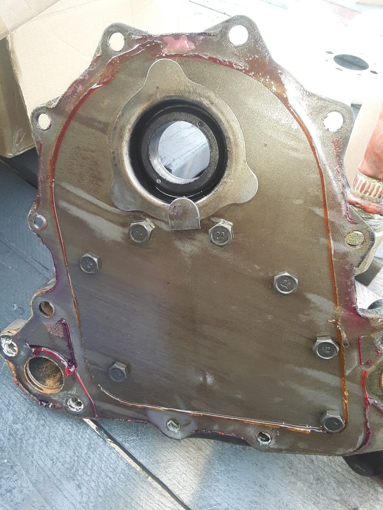
Back of Timing Gear cover shows no discoloration or evidence of any runtime on engine.