Wiring: Silicone Lubricant / Waterproofing

Military Surplus Silicone Waterproofing

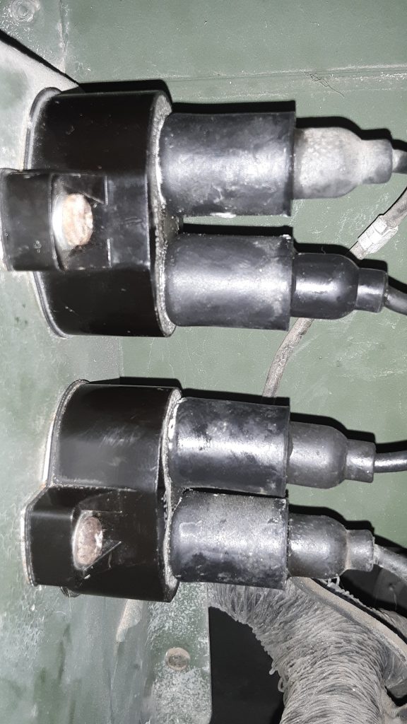
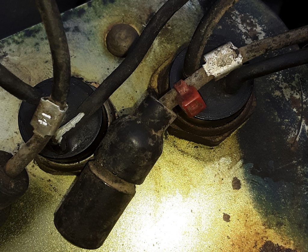
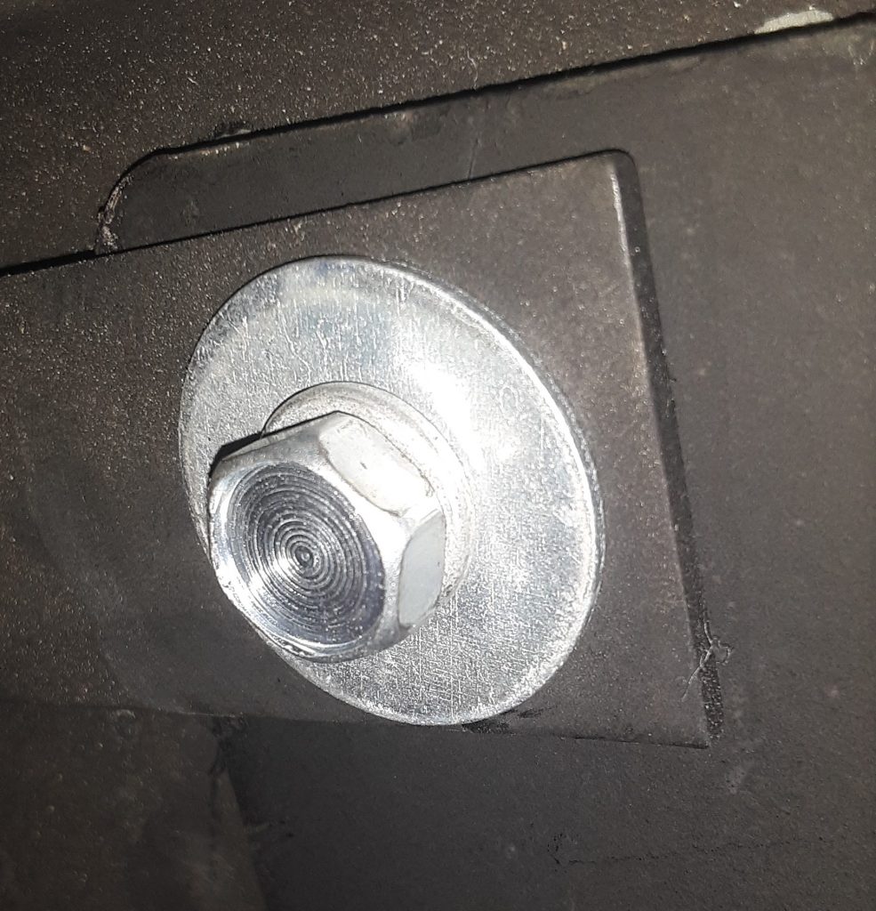
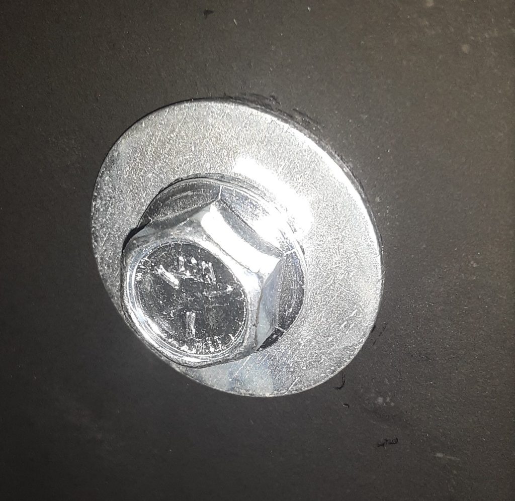
Anytime wiring with rubber boots are involved, it is always best to use a silicone lubricant. This assists in assembling the components, protects the rubber, and provides a further degree of waterproofing.

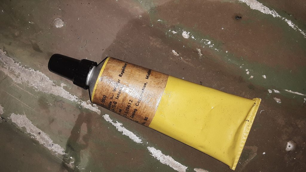
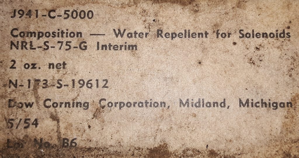
We have almost two cases of military surplus J941-C-5000 (also known as NRL S-75-G), which we acquired in the 1980’s. Since then, we have liberally used the silicone, and despite its age (Manufactured in 1954), it continues to be usable. Not bad for a 65 year old product!

We were unable to find further information of any kind on this product, however we have 30+ years using this material and have had superb results.

UPDATE: NRL S-75-G Interim was developed in World War II as a waterproofing lubricant to prevent machine gun failure caused by moisture freezing in solenoids at high altitudes (-20 F temperatures). (these failures are indicated as affecting the Cal .50 M3 and the 20 mm M24A1 Gun).

“The material is an open chain methyl silicone having a viscosity of 20 cSt at 77°F, and 300 cSt at -65°F, and a pour point of -75°F. Dodecane phosphoric acid (0.1 percent by weight) was added for lubrication. This material was labeled NRL S-75-G Interim.” Per: AMCP 706-26 at page 8-2 (Engineering Design Handbook, Guns Series, Automatic Weapons, Headquarters, U.S. Army Materiel Command, February 1970 [Document unclassified, but not marked as publicly released]).

Wiring: Circuit Breakers

As the breakers currently mounted in the HMMWV are around 30 years old (and have likely gone through countless fordings), we opted to replace them.

Newly installed 15 amp Klixon circuit breakers

These circuit breakers are “Klixon” style 15 amp breakers. The callout in the Parts Manual for these units are 5925-01-430-2318 [5925014302318]. However, this number seems to be obsolete. We were able to locate identical specification breakers under 5935-00-026-4767 [5935000264767]

These breakers have the same external dimensions and the same amp rating as the replaced breakers. The only difficult issue we had is that two of the connections would not release, and had to be replaced.

Interchange: Bow to Soft Top Rails

The screws attaching the bows to the side rails (Fig. 321, Item 6) calls out as 5305-00-059-3659 [5305000593659] with a general fastener number of MS51958-63 is essentially a 10-32 x 1/2″ pan head screw. Although we feel a standard 10-32 screw would be sufficient, we were able to source a number of the actual fasteners designated MS51958-63 at around the base price of the fastener from major vendors.

Although it is highly likely that a standard 10-32 screw would suffice in this application, we feel that use of the correct military fastener may give a slight performance advantage in both strength and corrosion resistance.

Of note, however, the fasteners we acquired indicate they are stainless, which is generally of a strength equivalent to a Grade 5 bolt. (of course, this depends on the type of stainless). We believe the vendor has mistaken plated fasteners as stainless. The packaging of the fasteners state they are MS51958-63. We have not reviewed the specifications of this fastener, but are of the opinion that even if stainless, they should suffice for holding the bows to the side rails.

Interchange: Soft Top Side Rail Screws (NAS1635-3LE12)

The screws at the front, middle, and rear of each rail are called out by different part numbers in the TM. The front screw (#1) 5305-01-210-6249 [5305012106249] with a manufacturer P/N of PL25D02P12 was not locatable.

The screw at the rear of the rail (#10) 5305-01-117-3396 [5305011173396] was similarly unlocatable, however we were able to locate this screw by its manufacturer P/N of NAS1635-3LE12. This is essentially a #10-32 x 3/4 screw. However, this has pre-applied locking compound. Additionally, we surmise this screw probably has a higher tensile strength than a standard 10-32 screw as it is an aircraft fastener.

As for the PL25D02P12 fastener called out for the front connection, at least one vendor (Kascar/real4wd.com) lists the NAS1635-3LE12 as an interchange. (at time of post, searching for the PL25D02P12 fastener comes up as NAS1635-3LE12) See: https://real4wd.com/store/catalog/search.aspx?keywords=PL25D02P12

In other words, we are comfortable that since both fasteners specifications are as a self-locking 10-32 x 3/4″, that use of the NAS1635-3LE12 is proper. There are apparently 50 in a box, and we have ordered 4 boxes to keep in stock.

Wiring – Preparation for Dash Wiring

Rapco “686” Tan applied to dash and vent areas. Note: Paint is still wet, when dry it is completely flat.

Prior to assembling the gauge cluster, lighting switches, filter minder and other connections, we prepped the existing CARC to accept paint. Special attention was paid to masking the window rubber, as paint can rapidly degrade it. This was painted in Rapco “686” Tan (which corresponds with FS 33446).

By pre-painting the dash and vent areas, it ensures an even color when these areas are masked off for complete vehicle paint.

Renovating Shifter Controls: Transmission Shifter Bushing

As our shifter was frozen solid, it required use of a hydraulic press, hammer, and punch to dissasemble the shifting mechanisms. In the process, we ended up destroying both the shaft and the bushing.

This bushing 3120-01-191-3232 [3120011913232] (indicated by red arrow) is made of thin nylon. Although after looking at it, we could have replaced it with an oilite or brass bushing, that would require machining of the shifting bracket. We then attempted to source the bushing using the NSN with no luck. However, we were able to located the part (currently available for order) from the manufacturer using the part number 10L18F. Applied Industrial Technologies carries this part available at https://www.applied.com/c-brands/c-thomson-industries/10l18f/Thomson-Nyliner-Bearing/p/101610126.

Renovating Shifter Controls: Reverse Light Switch

Early shifter control for basic and A1 versions

The transmission shifter in our M1038 was frozen, in that the release button could not be depressed to release the shifter. Additionally, the lever 2520-01-189-1064 [2520011891064] (Fig. 99, Item 16) was broken at the connection point. After removing the entire assembly, we noticed that this was an atypical shifter in that it had not only the safety switch 2920-01-249-3492 [2920012493492](Fig. 99, Item 20), but also a reverse light switch (not shown in diagram).

Shifter showing neutral safety switch and reverse light switch. Reverse switch is the right arrow.

It is our current understanding that the reverse light switch was used only on Marine HMMWVs, but that it is also desirable for on-road civilian use in states that require a functioning reverse light. The lead from one of the wires was 467 (whereas the neutral safety is 14). Of note, the hole for the reverse switch appears to exist in all of the housing assemblies (Fig. 99, Item 10). (See diagram). Of further note, the switch appears to be the same as the neutral safety other than there is a bushing installed to allow the smaller switch to be installed in a larger hole

Arrow showing reverse light switch. Note bushing surrounding switch.

From this, it appears that a reverse light switch can be installed in any of the earlier shifters. Once we identify the threaded bushing dimensions, we will post it. It seems relatively difficult to source the reverse light switch as opposed to the neutral safety switch.

Neutral Safety Wire #4, Reverse Light Wire 467

Splash Shield Supplemental Armor -LH Side

When installing splash shield supplemental armor 9515-01-189-9728 [9515011899728] to the left hand splash shield, it is required to eliminate the access cover 5340-01-457-0459 [5340014570459] by removing the three screws 5305-00-115-9934 [5305001159934] (MS51849-55) indicated by the red arrows that attach the access cover to the splash shield.

Failure to remove the access cover when installing the supplemental armor will result in an incorrect fit, and possibly damage to the splash shield. Additionally, the access cover cannot be accessed because it will be blocked by the armor.

Install Supplemental Armor on Splash Shields

A HMMWV radiator, as well as the cooler, are rather expensive. Although the splash shields do offer some protection from rocks and debris thrown from the front wheel, they are probably limited to offering protection against little more than water.

Plastic tends to break down over time and exposure to elements. Although our side shields appeared serviceable, we opted to install supplemental armor to provide additional protection.

The picture below shows the RH side supplemental armor 2510-01-189-9744 [2510011899744] installed over the side shield.

There are two additional side shields available for each side. The standard (or basic) radiator shield for the RH side is 2510-01-185-7946 [2510011857946]. The supplemental armor is a little over twice as thick, and is called out as “armor plate.” The basic plate appears to be manufactured from mild steel.

Supplemental armor for the LH side is 9515-01-189-9728 [9515011899728], whereas the basic is 2510-01-185-3107 [2510011853107].

We also updated and improved the fasteners attaching the supplemental armor to the splash shields.

In the picture above, we did utilize the 5/16-18 x 1″ self tapping screw 5305-01-253-2993 [5305012532993] called out for attachment to the air lift mount. However, the TM calls out for a 5/16″ washer over a 3/8″ washer. We instead chose to use a 5/16″ lockwasher and a 5/16 x 1 1/8″ fender washer. In our opinion this offers an esthetic improvement as well as ensuring that the load is evenly distributed. We are unsure as to why this was not done instead of stacking two different size washers. Regardless, our substitution is appropriate.

On the other positions that did not call for a self tapping screw, we substituted 5/16-18 x 1″ “Wiz” bolts and nuts (also known as serrated flange) in place of the regular bolts called out for in the TM. Because of the serrated flanges, these act to some degree as a lock washer, and the flanged head helps distribute load on the inner side of the splash shield. Also, again we used 5/16 x 1 1/8″ fender washers in place of the stacked washers called out.