Project M1038: Body On, Back to Shop

After re-installation of the body to the chassis, and installation of the body mount bolts, a forklift was used to place the HMMWV back onto the lift in the front shop.

As it had recently rained, we had some difficulty with the forklift pushing the HMMWV back into the shop and up onto the lift. As you can see, the entire front of the HMMWV is off the ground to enable the forklift to maneuver the vehicle into the shop.  Because of length of the HMMWV and the location of the forklift drive towers, a somewhat “running start” was required in order to place the vehicle back on the lift.  During this process, the fork interfered with the water pump pulley, bending the water pump shaft.  However, that is a relatively inexpensive part, and easily replaced on the vehicle as it currently exists.  In fact, the water pump shaft could have already been damaged in transit as was a number of other powertrain accessories. (see earlier article).

Dec. 9, 2018, Project M1038 back on lift rack, and ready for final assembly, wiring, and installation of cooling stack and hood.

Project M1038: Body to Chassis – Lifting with Crane

As noted in prior post, the windshield had been removed to eliminate any opportunity to damage it.

After lifting the body, the chassis was simply rolled underneath, and the body carefully lowered onto it. 

Body re-installed onto chassis. (Note roof hanging across front seats because front windshield was removed to prevent damage)

View of re-installed body from right side front.


Project M1038: Body to Chassis – Lining up and readying crane

As the body had been previously removed to make it easier to install engine and work on running gear, it was now time to put the body back on.

A forklift was used to tow the chassis out and line it up under the body:

Once lined up, the crane was brought in to hook up to the body.

Tom Grundman pulling the line from the crane.

Rigging was placed on the body at the front firewall, the two load loops behind the rear seats, and one strap to the rear of the vehicle. (the rear part of the body is designed to flex and cannot support itself, but is not heavy and only took one strap to support it.

Tom Grundman rigging the body for re-installation

As we hooked up straps, we decided it would be prudent to remove the windshield to prevent any possibility of damage.

Interchange: Power Steering Return Hose


Determining what size hose is required to route to the cooler and the fan clutch solenoid is confusing based on the parts manual.

For example, the fitting from the return line from the cooler to the fan clutch solenoid (Fig. 178, Item 1) 4730-00-789-0951 [4730007890951] is designated as manufacturer p/n 110-03604 which is apparently an Eaton Aeroquip 90 degree brass fitting of 1/4 NPT x 5/16 hose barb.

However, the hose specified to go over the barb (Fig. 178, Item 7) is P/N 6490610019 which translates into AM General 5741209, which is assigned NSN 4720-01-186-2358 [4720011862358] and is also known as GM 6210M.

Per General Motors Corporation, the 6210M specification covers “…a 9.5 mm inside diameter hose made from textile reinforcement and synthetic rubber for use in hydraulic steering applications as a flexible connection between the power steering gear and the power steering pump or pump reservoir.”

The closest fraction to 9.5 mm is 3/8, which is exactly 9.5250 mm.  Whereas 5/16 = 7.9375 mm. We checked the dimensions of other fittings called out for use with this hose (e.g., 4730-01-481-6278 [4730014816278] ).  Its dimension is stated as “NOMINAL INSIDE DIAMETER HOSE ACCOMMODATED 0.290 INCHES 2ND END” or, slightly less than 5/16″.

We further found in the parts manual other references to P/N
6490610019, which gave an alternate AM General part number of 12338330, which is again defined as flexible hose (along with a suffix -X number) of 3/8″ diameter with applications ranging from Air Horn to CTIS (-7),  transmission (-1. -2, -5),  and power steering (-6, -9).

It seems axiomatic to use a 3/8″ hose with a 3/8″ barb fitting, not a 5/16″ barb fitting as the call out indicates.  However, throughout the parts manual it systematically calls out for 5/16″ barb fittings.

We are of the opinion that using a 5/16″ barb with a 3/8″ hose is an error. The barb itself is 1.5875 mm smaller diameter than the hose, and that means that the hose would have to be tightened considerably just to contact the shank of the barb.

We inspected the old and damaged hose removed from the 1038. There were no markings, but it appears to be a 3/8″ hose. Further, 3/8″ power steering hose is considerably more readily available commercially (and at considerably lower cost) than the 5/16″ version.

We ordered and have on hand Gates 350010 Power Steering Return Hose (which is a S.A.E. J189 Power Steering Return Hose
3/8″ x 25′ bulk package).

We can find no valid reason for the mismatch between the sizes of the fittings and the hose called out in the parts manual.

We will update or change our findings regarding the discrepancy between the parts manual call out of 5/16″ barb fittings and the use of 3/8″ hose as we complete the hydraulic plumbing of the 1038.

Interchange: Fan Quick-Disconnect


In order to make belt changing a little simpler, AM General incorporated using a quick-disconnect (Fig. 178, Item 17)  4730-01-399-0241 [4730013990241] on the hydraulic hose 4720-01-189-0853 [4720011890853]  leading to the fan clutch.

Although the quick-disconnect can be sourced as 12342947, it appears to now be marketed as an H1-62 coupler (a Parker number for the female half). This number is the female half of a 1/8″ hydraulic coupler. (Fig. 178, Item 17 actually depicts the male and female halves together) If you are lacking both parts, or if you just need to replace, search for an ISO-B hydraulic coupler in 1/8″ thread.

All couplers marked as ISO-B, regardless of manufacturer, should be interchangeable as long as they adhere to the ISO B standard (ISO 7241-B).

Above pictures are of Foster FHK Series 1/8″ H1S K1S Steel ISO B Hydraulic Quick Connect Coupler sourced from HPC in Elgin, IL.

A study in Steering Gear Bolts

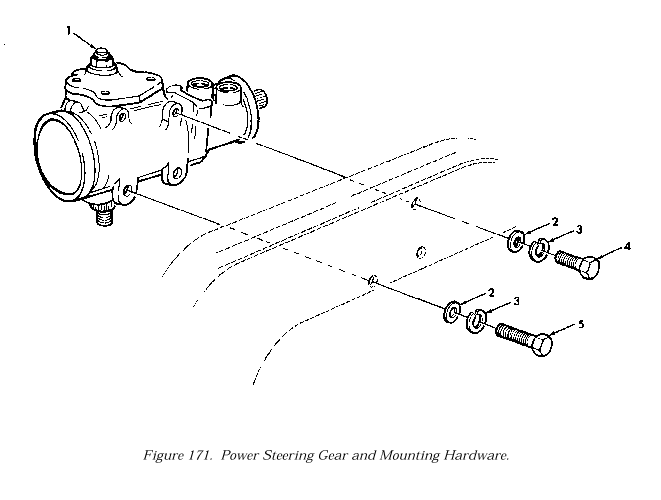
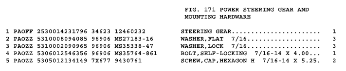
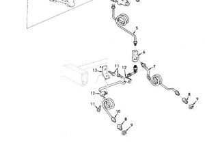
As discussed in an earlier article, there are two 7/16-14 x 5.25 bolts 5305-01-213-4149  [5305012134149]  and one 7/16-14 x 4.00 5306-01-254-6356 [5306012546356] required to mount the steering gear to the frame. The 5.25″ length can be sourced as GM 9430761, however the 4″ bolt as MS35764-861 is not easily sourced, but 4″ long bolts are a standard length, unlike the 5 1/4″ length.

This article is about whether the length is that critical.  We do not believe so. (but read “word of caution” at end of article) For restorative purposes you may want the length to be as close as possible, or if not, to otherwise serve as a useful upgrade.

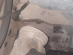
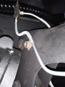
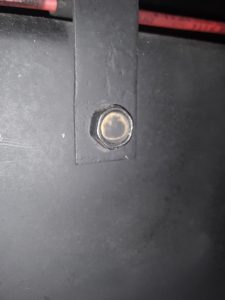
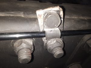
The picture below shows the clearance against the steering box when using the 4″ long bolt:

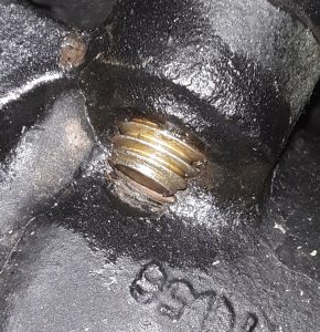
Note that the bolt extends through nearly 1/4″, and would likely have extended slightly further had we used a standard Grade 8 SAE washer instead of the “extra heavy” ones that we did. Further note that the end of the bolt can actually butt against the housing, the threads do not go above or across the top of the housing. Ensure that the end of the bolt does not butt up against the housing, which will result in a false reading with a torque wrench.

Note there isn’t a tremendous amount of clearance between the end of the bolt and the housing itself.  You can see that it was threaded into the housing so the bolt didn’t bottom out.

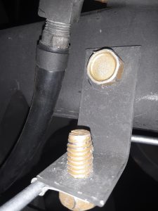
Ensure that whatever bolt/washer combination you use in the 4″ location that the bolt does not deadhead against the housing. (this would likely result in the upper boss of the steering gear not being drawn tight into the frame as well as causing an erroneous reading with a torque wrench.)

What about substituting longer or shorter bolts?

For the 4″ length bolt, the next shorter standard length would be 3 1/2″, and although that would at least partially engage most of the threads in the boss, we would advise against it except under emergency circumstances since this boss is the only one of the top two that even gets a bolt.

Our opinion changes slightly on the two lower 5 1/4″ length bolts.

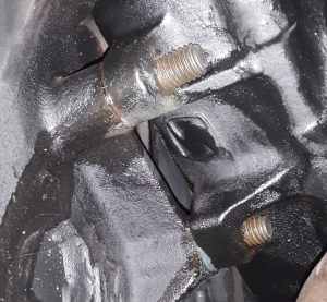
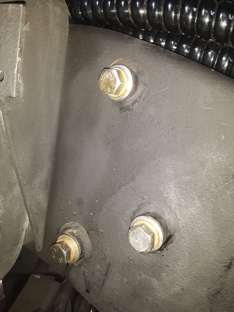
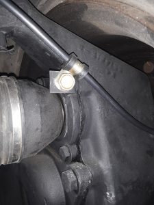
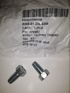
In the picture above, you can see how far the 5 1/4″ lower bolts extend past the bosses in the steering gear. There is no doubt that a 5 1/2″ bolt might work (assuming the threaded section of the bolt is long enough and doesn’t bottom out in the boss).

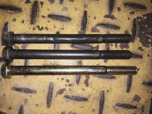
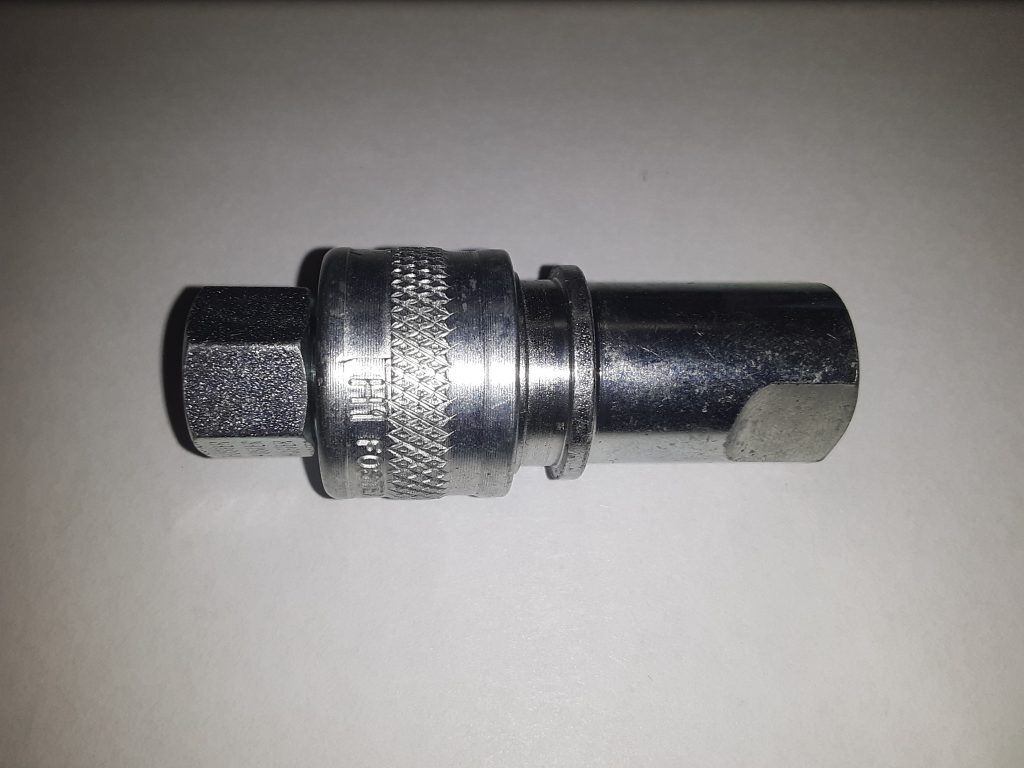
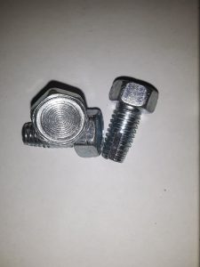
Pictured above are (top bolt), the sole 5 1/4″ bolt remaining in the M1038. The middle bolt is the GM 9430761 discussed above, and the bottom bolt is one supplied by one of the “big 3″ suppliers. The bottom bolt is in fact, a 5 1/2″ length bolt. Because we had concerns that the threads would not be long enough (and bottom out in the boss) we chose to not use the 5 1/2″ bolt and acquired the proper length of 5 1/4.” It is likely that people may have erroneously replaced this bolt with the incorrect length which could potentially lead to a dangerous situation.

In our opinion, the most rearward of the lower bolts could be a 5″ long bolt without any adverse issues. As we installed it, it is nearly 1/2″ past the boss. The frontward one could also likely get by with a 5″ length bolt and still thread completely into the boss.

A word of caution, however, is that the steering is one area you don’t really want to take risks in. You limit your liability and ensure vehicle safety by using the correct fasteners, or at least the correct length of fasteners called out by the manufacturer.

Steering Gear Mounting

As luck would have it, the steering gear on our project M1038 had only one bolt holding it to the frame. Fig. 171 (of TM 9-2320-280-24P-1), shows two different bolts attaching the steering gear to the frame.

The sole remaining bolt was 5 1/4″ long. According to the call out in the Parts Manual, this corresponded with Item 5,  5305-01-213-4149 [5305012134149].  Unfortunately, however, it was virtually impossible to locate a 5 1/4″ Grade 8 bolt, as the common sizes are 5″ or 5 1/2.”

Although some of the “big 3” indicate that a bolt kit is available for the steering gear fasteners as 5745684, when we ordered it, we were told it was on backorder from AM General, and at least one seller indicated that the kit was simply “discontinued.”

We cancelled the backorder and tried sourcing again. We were able to find a seller on eBay selling “GM Hex Head Cap Screw Bolt 9430761  7/16″-14 x 5.25 Grade-8 UNC.”

As it turns out, 9430761 is the manufacturer’s part number for this bolt, and being as it is a GM steering box, it makes sense that GM would be the supplier. Although we had to purchase five bolts, when we technically only needed one (there was one remaining), we have extra bolts in the event they are needed in the future by us or others.

The callout for the remaining bolt (Item 4) is 5306-01-254-6356  [5306012546356] which is described as: “BOLT, SELF-LOCKING 7/16-14 X 4.00″  Although 4″ is a common length, we were not able to source this specific bolt (MS35764-861) and substituted it with a standard 7/16″-14 x 4” Grade 8 bolt.

It is not uncommon for steering boxes to loosen up over a period of time. We originally opted to use Nord-Lock lock washers in place of the split lock washer. However, in the interest of attempting to keep the project as original in appearance, we instead used Grade 8 split lock washers and heavy 7/16″ Grade 8 SAE washers instead. All three bolts were installed with blue loctite and torqued to 60 ft-lbs.

Torque specifications and use of blue Loctite are as recommended by flashoffroad.com in their chart located at:  http://www.flashoffroad.com/Maintenance/Specs/torqueSpecs/HMMWVTorque.htm  (opens in new window)

Installation of the RH Front Brake Line

The front brake lines on the 1038 had already been scavenged prior to our restoration of it.  After ordering the proper brake line 4710-01-186-1016 [4710011861016] also known as 5584142 (Fig 159, Item 10), and going to install it, it was somewhat confusing based on the parts manual.

From the parts manual, it appears Item 10 goes in front of the crossmember.  However, after researching brake lines on the 998, we learned the tubing starts on the rear side of the crossmember and loops through to the front side as indicated in the following picture.

Below is the front RH brake line mounted in the M1038.

Note the use of the 3/8-16 self threading screw (or bolt) 5305-01-236-4349 [5305012364349] discussed in another article.

The lesson is exploded views in the parts manual are not always accurate. A big example of these inaccuracies is the rear vent lines (Fig. 149), which appear to have been flipped left to right. We will address these discrepancies in another article.

Brake and Vent Line Fastening Bolts

Brake lines and vent lines are attached to the chassis through use of a 3/8-16 self threading bolt. The NSN associated with this is 5305-01-236-4349 [5305012364349]. The manufacturer part number for this is 172482.

This bolt is called out a number of times in the parts book, and in at least one place it is referred to as: SCREW, TAPPING 3/8-16 X .62. It is primarily used to hold down brake line and vent line loop clamps, and is even used on each hub to attach the vent line loop clamp to the hub.

There really isn’t an easy substitute that looks or works correctly on this.  We found at least once on the 1038 where a mechanic (or other person) tried threading a 3/8-16 bolt into the frame to hold a cushion clamp on, but it simply would not tighten.

We have ordered these screws from some of the “big 3,” and they worked, although they seemed to be a bit longer than the call  out. And after we acquired a bag of 100 of the proper screw (with the proper NSN), it was noted that the ones ordered from one of the “big 3” were slightly longer.

As these screws range from $0.16 to $0.25 per screw, we recommend using the correct screw as called out by the manufacturer.  Because of its low price, the damage that could be caused by using an incorrect screw would far exceed the cost of using the correct fastener.

Upgrade: Fuel Injector Return Lines

The 6.2 and 6.5 commonly will leak from the injector fuel return line hoses.  (Fig. 11, Item 23). There is no NSN assigned to these hoses, rather they are cut to length from hose p/n 9439046. As these hoses age and dry out, they tend to crack and break, resulting in fuel leaks on the engine and onto the exhaust manifolds.

We installed new upgraded replacement hose sourced from Badger Diesel in Kenosha, Wisconsin. (262-859-2444). Unlike the original hose, the extremely small (and easily distorted) hose clamps 4730-00-150-6118 [4730001506118]  are not required as the hose fastens securely to the fittings by itself..

Badger markets a complete kit to replace the return hoses as Badger Diesel 6265RLK. According to Badger, “This kit includes more than enough line to do the full job with 8″ of line per injector rather than the 3″ that the competition offers having only enough to barely do half the job. Thats 266% more line!” Badger further points out this hose is made in Germany, not China as is apparently their competitor’s hose.

In our opinion, this hose is a definite upgrade from the factory hose, and not having to use the extremely small and difficult-to-use hose clamps is a plus.