Upgrade: Replace Transfer Case Cooling Line Hose Clamps with Fuel Injection Clamps

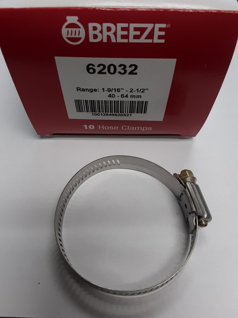
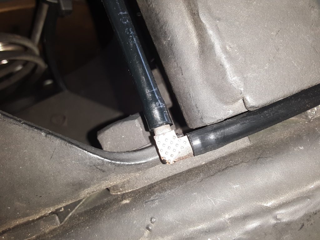
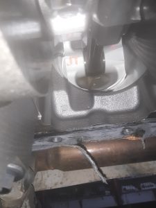
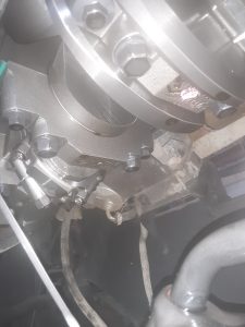
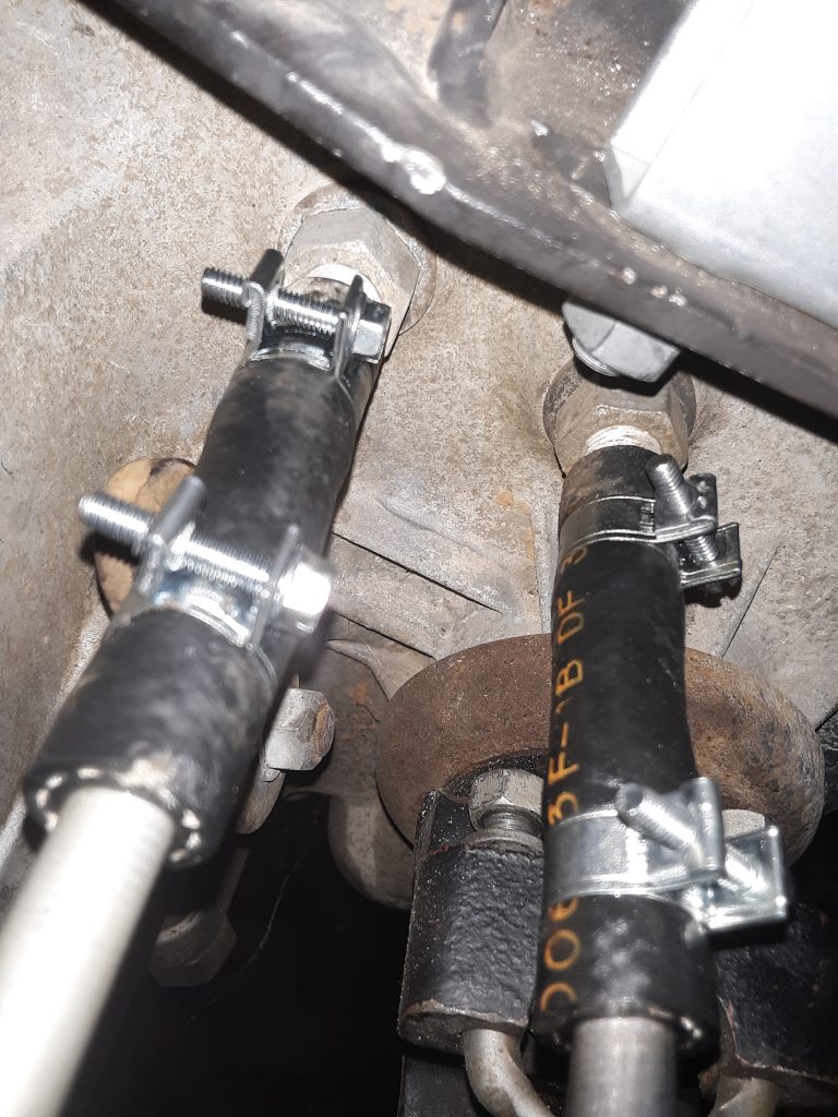
A common problem with standard hose clamps is that they will often tighten up unevenly, cock sideways, and require excessive torque to seal.  Here, we have replaced the hose clamps on the transfer case cooling lines with fuel injection clamps (14-16mm range). While these generally cost considerably more than a standard hose clamp, they offer improved sealing and reliability. They can be bulk sourced at a number of online sites, often at a greatly reduced price.

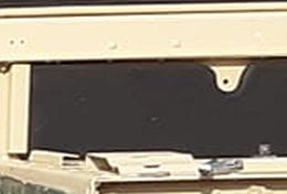
The picture aboves shows where we replaced the original hose clamps 4730-01-118-8278 [4730011188278] with 14-16mm (9/16″-5/8″) fuel injection clamps.  The original clamps were apparently installed at the factory from the top side of the frame prior to installing the body. We re-oriented the clamps so that they would be easier to adjust or remove & reinstall from under the vehicle.

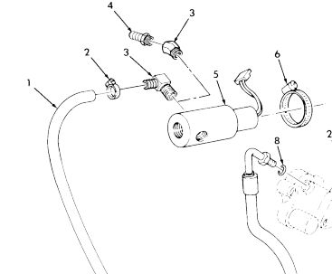
These are still the original hoses that came with the powertrain. Although we had new hose to replace it with, we did remove and inspect the hoses. The hose itself remains “live” and showed no sign of cracking, so we retained the original hoses and installed the new clamps.

Interchange: Fan Solenoid Mounting Clamp to SAE Size Hose Clamp

Both the fan control solenoid and mounting clamps had already been scavenged from the 1038.

Finding a replacement solenoid (Fig. 177, Item 5) 4810-01-192-5817 [4810011925817] was relatively simple, and just about every supplier stocks it.

It would be nice to find a cost-effective substitute, but as of yet, we have not located one that would be both cost-effective and a simple retrofit.

The clamps holding the solenoid to the body were also missing. The parts manual (Fig. 177, Item 6) does a call out for 4730-00-204-3491 [4730002043491] but fails to specify its size.

After researching the NSN and manufacturer number of C32P, we identified this clamp as a 40-64mm or (1 9/16″ to 2 1/2″) stainless gear clamp. This clamp is an SAE 32 hose clamp. We acquired a box of ten Breeze brand clamps for our application, although only one is required. In fact, it appeared during our research that Breeze or its parent company may have actually been suppliers of this clamp to the government as 4730-00-204-3491.

Vent Tubing: Hub, Differential, Transmission and Transfer Case

Our project vehicle had been stripped of most of the vent lines, and some it appears may never have been correctly installed.  (See: missing fitting and hose on front differential vent caused water infiltration).

Accordingly, we had to source and locate replacement or substitute hose and tubing for installation. All of the hoses and tubing are indicated in the parts manual as either P/N CPR104420-1 or P/N RB1450-1-4IDX1-20D. 

Upon visual inspection, CPR104420-1 was identifiable as air brake tubing used on semi-trucks. One of the brand names for this is an Eaton product called Synflex®.

Synflex® used to vent rear differential and hubs and transfer along frame. 

Upon further research, it was determined that CPR104420-1 is 1/4″ diameter tubing. (note this tubing is measured by O.D., not I.D.) Whereas CPR104420-2 is 3/8″ diameter. (CPR104420-2 is used as the main tube running parallel to the frame to vent the fuel tank).

We were able to identify RB1450-1-4IDX1-20D as being manufactured by Armstrong, and carries an NSN for bulk lengths as 4720-00-684-4033 [4720006844033].  This essentially is a durable 1/4″ I.D. hose, which has the appearance of 1/4″ fuel hose or similar.

There is a number of vendors that make a suitable replacement, although we noted the caveat of not using fuel line because it may not remain flexible enough over time for use on the front hubs. (they will constantly be flexing as the vehicle is steered).

It was suggested to us to consider use of silicone vacuum or vent hose.  Silicone hose was simply not readily available at the time of manufacture and design of the HMMWV. Vendors cautioned against using silicone hose for oil or fuel carrying. The primary reason for not using silicone for fuel is that it simply isn’t rated for pressurized fuel. We determined that 1/4″ silicone hose would be appropriate for venting purposes, and noting its widespread use in commercial and agricultural applications gave us a level of comfort of its reliability.


Front RH vent line from hub attached to tee fitting on frame. Note use of original style clamp 4730-00-954-1251 [4730009541251]


M1038 Project: Finishing up hubs

Always have extra seals when re-sealing hubs. Even though we had five (5) seals on hand, we ended up destroying two of them, and had to get additional seals.

In these pictures, the LH rear hub has been cleaned and ready for final reassembly.  Of note, all four corners had the very original 4-slot spindle nuts, and we replaced the locking rings and used 8-slot spindle nuts on reassembly.

Left hub, ready to put seal and spindle back in.

Left rear hub

M1038 Project: Engine Pan Drop

The engine oil pan was crushed during shipment, necessitating replacement. Whether that was the fault of the shipper or the seller, we don’t know. After finally locating a new replacement pan, the old one was removed. This engine does not look like it could have over 100 hours. Most likely, it appears that whatever HMMWV this powertrain came out of, it was likely a 6.2 that was upgraded to the 6.5NA and then sent for scrapping.

Internal view of 6.5NA showing virtually no wear or use.

Picture showing extremely clean, extremely low hour engine internals.

Update  (Dec. 15, 2018):  As we had to remove the timing cover to replace the water pump, we were afforded another view into the internals of the engine:

As visible, this is clearly a fresh engine. Not even the paint marks have discolored from oil and heat, and the Loctite 518 (or similar) had not been washed away.  There is a slight amount of rust visible at the top of the upper timing gear caused by ambient air entering through the oil fill, but this should be considered normal, especially on an engine obtained from a de-mil.

Back of Timing Gear cover shows no discoloration or evidence of any runtime on engine. 

M1038 Project: Engine Installed

Having acquired an early model Marine M1038 (circa 1985) quite some time ago, we finally got around to installing an updated powertrain.  We chose to upgrade the engine to a 6.5NA. (realizing it is detuned, but also has less parts to fail). This retains the 3L80 (TH400) originally supplied. Additionally, this updated the Transfer Case to the AMG 242 model.

Engine installed and chassis freshly painted with CARC substitute 911 (flat black) on September 27, 2018.

M1038 Project: Stripping Chassis and prepping for new powertrain

After the body was removed and set outside on stands, the chassis was negotiated onto the lift with a forklift. Once on the lift, everything that needed to be gone through was removed. Unfortunately, not only was the vent line missing from the front differential, so too was the fitting itself. This essentially made a funnel for water to infiltrate the front differential.

Both differentials were removed. The rear differential was re-sealed and re-mounted. The front differential was left off for a later rebuild.

Project M1038: The beginning

Somewhere out of the “bone pile” or off one of our other ranches, brother Tim towed in a relatively stripped HMMWV for us to work on as a project.

The powertrain was missing, as was the windshield, headlights, reflectors, seats, and lots of other stuff.  It was unloaded and taken out to the vehicle parking area. Our main website picture shows it being towed by the M998 on its way to the front shop with the four-poster lift.