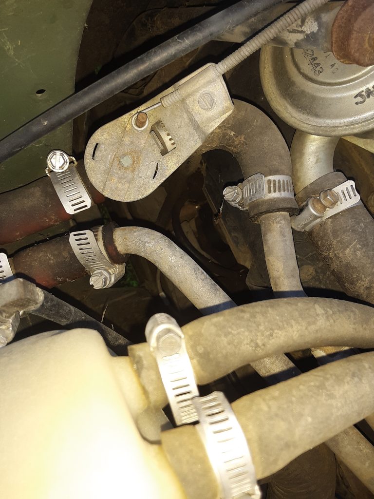
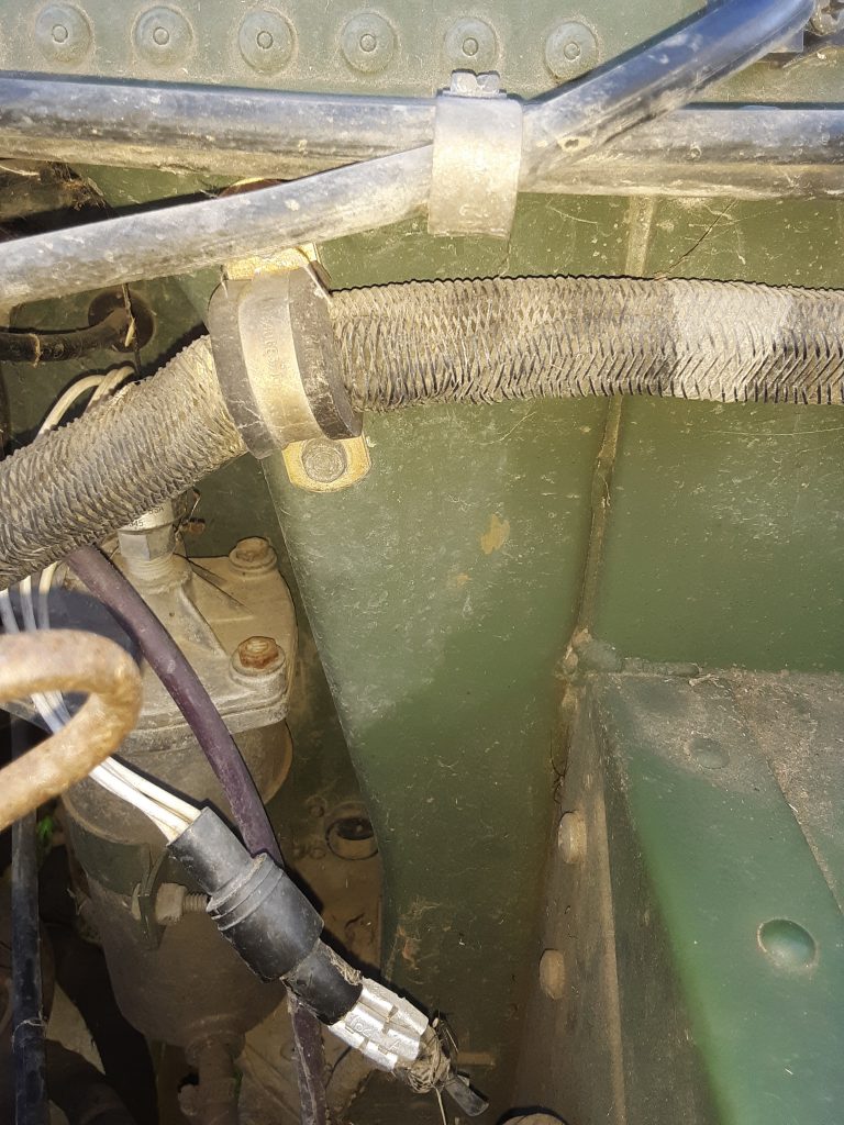
Above picture shows location and connection of heater control valve. Also visible are connections to surge tank and return from heater core. Upper RH shows the CDR valve.

Solutions, Upgrades, and Parts Interchange for HMMWVs
Above picture shows location and connection of heater control valve. Also visible are connections to surge tank and return from heater core. Upper RH shows the CDR valve.
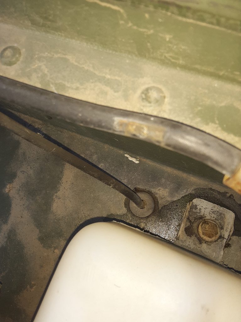
Above shows the entry location and grommet for the hose from the air filter to the filter status gauge.
UPDATE: The Project M1038 does not have a hole in this location. We are attempting to determine whether a filter status monitor was available in the early serial numbers, and if so, if the hosing was routed differently. Before we drill a hole, we will determine whether it would have been upgraded had it remained in service.
Views of Figure 84, View I (there are three according to parts manual), body harness to front frame (leading to hood wiring). Clamps are 5340-00-088-1254 [5340000881254] (MS21333-104). These clamps are 5/8″ inside diameter, 1/2″ wide band, with a 1/4″ mounting hole.

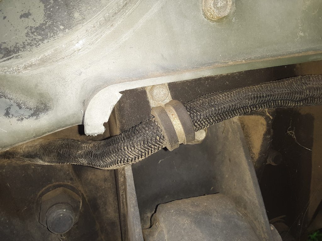
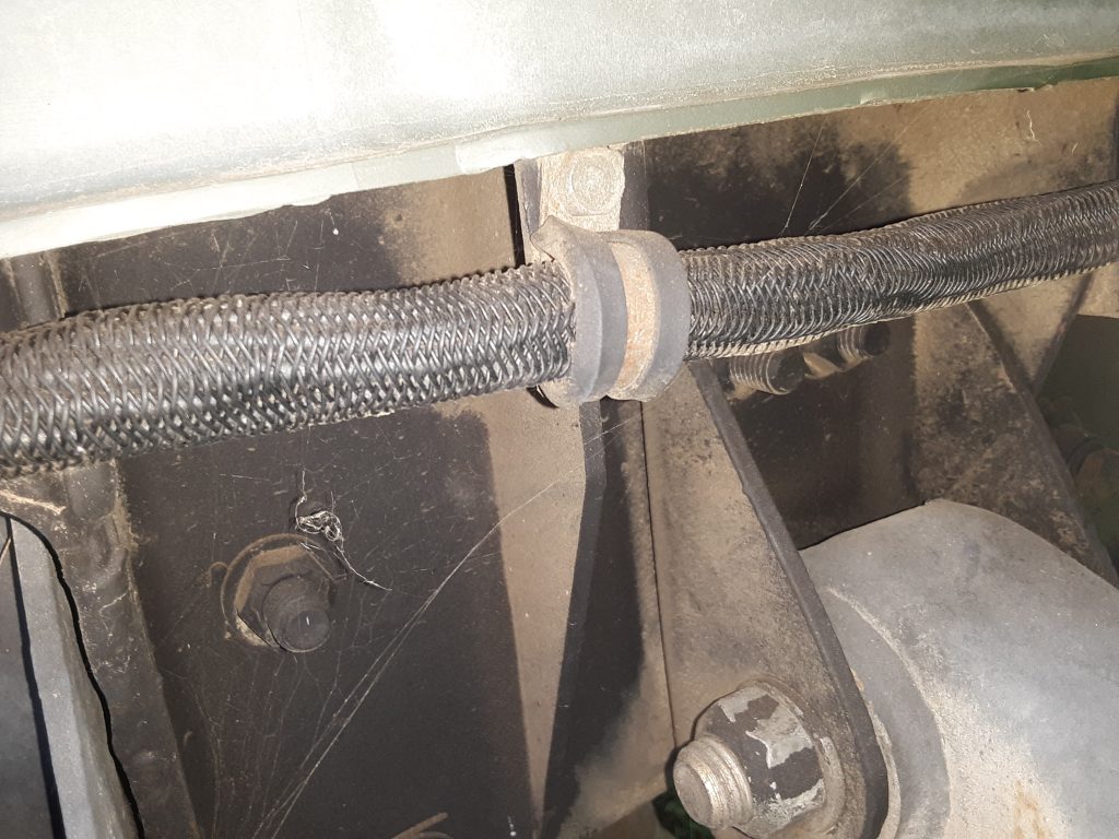
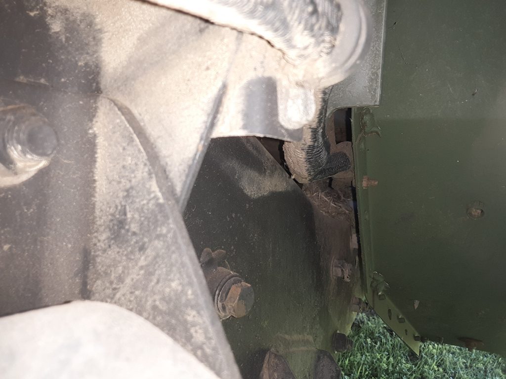
Above shows engine wiring harness attachment to engine with retaining strap 5340-01-213-4667 [5340012134667]. This is attached with two (2) self-tapping 1/4-28 X 1/2″ screws 5305-01-206-8401 [5305012068401].
Refer to Figure 75, View AE.
Above shows engine wiring harness attachment to body with retaining strap 5340-01-213-4667 [5340012134667]. This is attached with two (2) self-tapping 1/4-28 X 1/2″ screws 5305-01-206-8401 [5305012068401].
Refer to Figure 75, View AF.
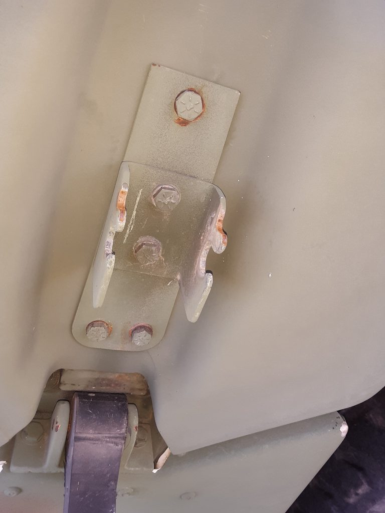
This shows the LH side of the hood, RH side is identical. This shows the STRIKE, CATCH 5340-01-189-9979 [5340011899979] bolted to the Mending Plate 5340-01-211-3132 [5340012113132] with three (3) 1/4-20 x 1 1/8″ bolts 5305-00-225-3842 [5305002253842] and two (2) 1/4-20 x 7/8″ bolts 5305-00-071-2505 [5305000712505]. Refer to Figure 202 of the parts manual.
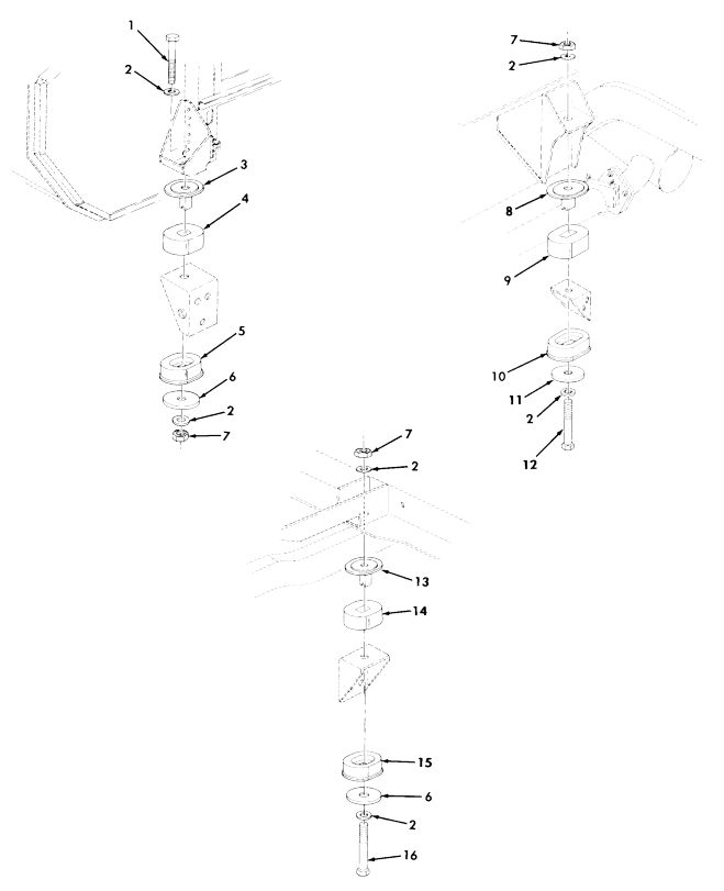
Body Mounts. The parts manual shows three different “spacers” or more accurately, washers (Fig. 196. Items 6 & 11), used underneath the lower body mount cushions.
Of these, there are several NSNs. For the Front LH side, it is 5310-01-476-9321 [5310014769321], which also carries P/N 12339248-3. The Front RH and the rear use 5310-01-252-7285 [5310012527285] (12339248-2). The intermediate mounts (the ones in the middle) call out 5365-01-214-4987 [5365012144987 5583215].
Other than the front left hand side (the most difficult mount to deal with because it bottoms onto the frame and can only handle a maximum diameter washer), we can find no reason for use of different washers at the different locations.
First, it is unclear what purpose these washers serve. We speculate that it is either to 1) spread the load across the metal portion of the lower mount; or 2) (in event of catastrophic mount failure), it would prevent the body from separating from the frame. There could also be some other reason we simply don’t know, but we have never seen washers used in this way for automotive purposes.
To be clear, we are not discussing the spacers used between the body and the upper mount to provide armor clearance on later versions.
After ordering all of the proper washers, two were on backorder status and we were only able to obtain two washers used for the front LH application, 12339248-3. (We like to keep extra parts in stock). This washer measured out at 5/8″ x 2 3/4″ x .250″.
Having only the LH washer/spacers, they measured at 5/8″ x 2 3/4″ x .250. The front LH definitely has a clearance issue, as that is the single mount with a “bucket” welded over the frame.
Comparing this washer to the lower months, it still covers the bulk of the metal on the largest mount, the intermediate mount 5342-01-186-7236 [5342011867236] (12339247-3).
Upon determining that the smaller diameter washer appears to also work in the other positions, and being unable to timely source the washers/spacers called out for the right front, intermediate and rear positions, we determined that a washer of 3″ diameter will both fit and service properly.
We will use the extra front LH washer in the front RH location, and ordered four 5/8″ x 3″ x .250″ washers to be plasma-cut by my brother, David Grundman. As the washer 5310-01-476-9321 [5310014769321] we do have appears to be galvanized, we will be powder coating the plasma-cut washers for corrosion protection.
We will update this posting should we find any issues with using the washers in the positions as described above. If anyone has any insight as to why different washers are utilized, we would appreciate hearing from you.
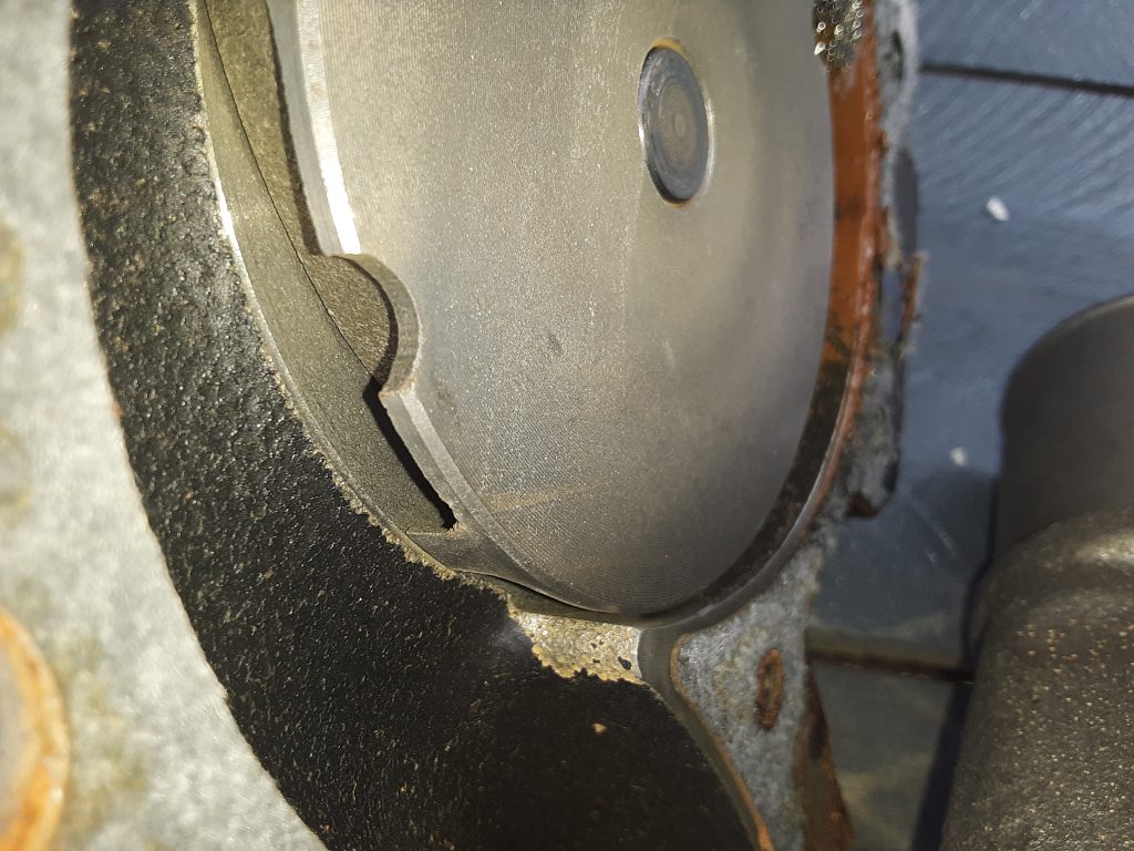
According to the Parts Manual, a rivet is to be installed into the upper weep hole of the water pump. (Fig 31, Item 6).
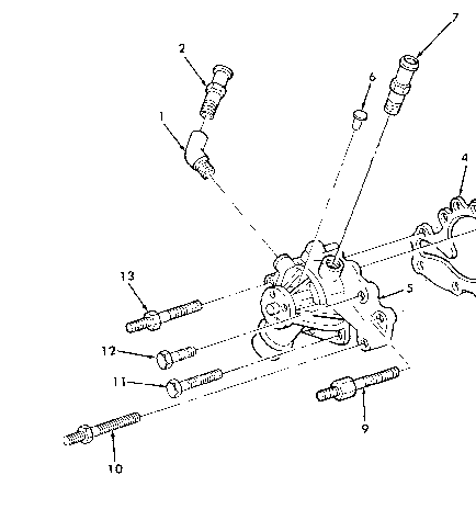
This rivet is 5320-01-218-0721 [5320012180721], and is described as RIVET, SOLID 1/4 X 1/2. This rivet is visible on the water pump we removed from the 6.5 NA. (between the coolant bypass fitting and the heater hose fitting).
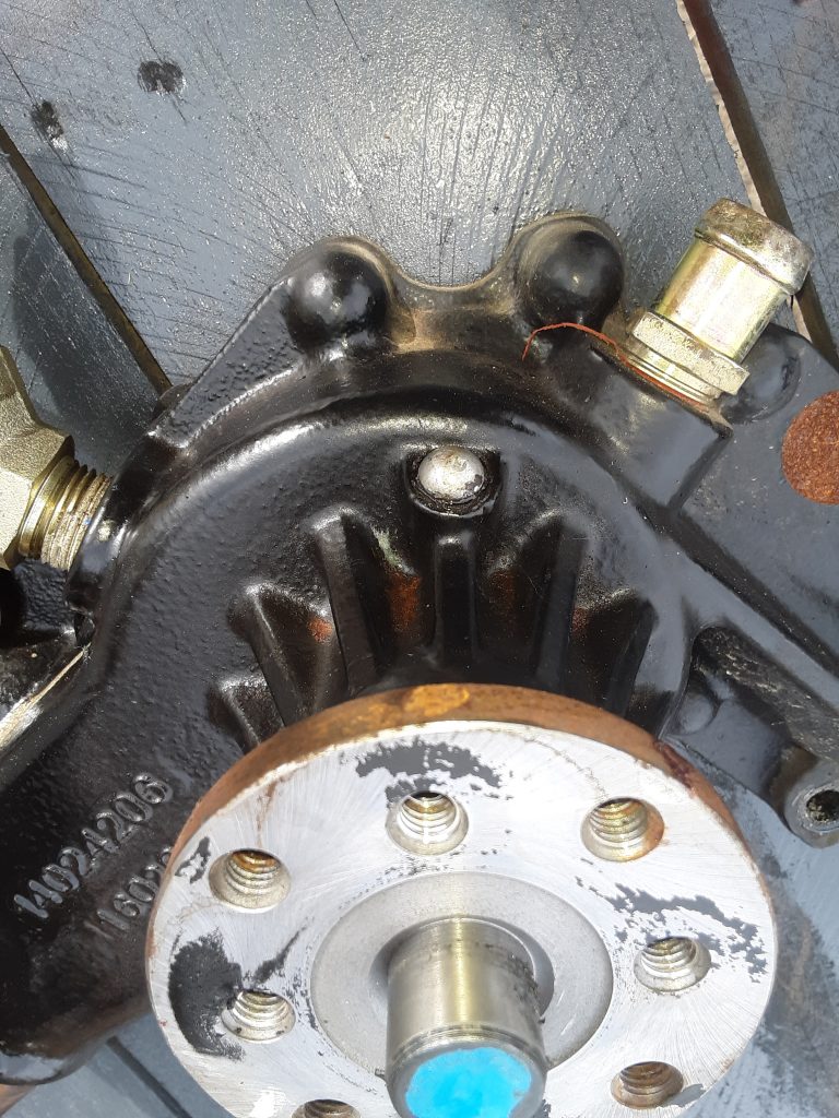
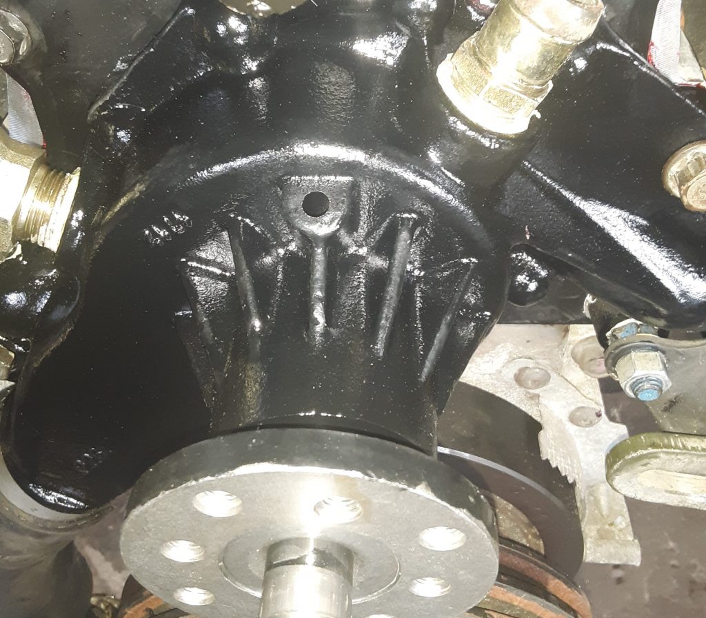
Our replacement water pump, as installed, did not have this rivet.
We removed the rivet from the original water pump by prying it out with a screwdriver. It appears that the rivet was held in (or glued in) using Loctite 518 or similar. (“grape jelly”). We noted that the 518 had not set up, either because the engine had not run enough to heat up, or it was simply the wrong material to use.
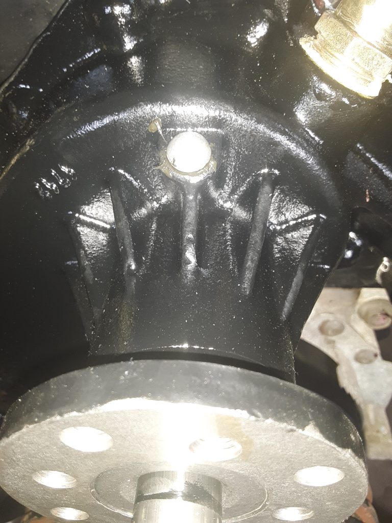
After removing the rivet, we installed it in our water pump using Permatex No. 2, which does harden up with air, but remains pliable. Although No. 2 has falled into disfavor over the years in place of materials such as RTV and pressure hardening sealants such as Loctite 518, we still find No. 2 suitable (and in some cases, superior) to modern sealants, and especially in this application.
We are unsure of the precise reason as to why the call out requires a rivet to be installed into the water pump. And this may explain the price discrepancy between interchange water pumps and OEM water pumps. In our opinion, moving the rivet from the old pump to the new one (or even buying a new rivet) makes for a considerably less expensive replacement.
I consulted with Tim Grundman of Big Dawg Diesel Worx, LLC, and he informed me that he had never seen a weep hole plugged with a rivet on any industrial or agricultural applications. And although this particular powerplant had not come from a vehicle with the fording upgrades, we speculate that the purpose of plugging the upper weep hole is to prevent contaminants from entering the weep hole and affecting the outer seal on the water pump bearing.
According to our research, this base water pump was used on a number of applications other than the 6.2 and 6.5 diesels. Likely there may have been an application where the water pump mounted upside down from this application, allowing the weep hole to show leakage regardless of position.
Further, it may be that under fording applications, plugging this hole prevents waterborne foreign material from lodging into the front of the water pump and aggravating seal damage.
Regardless of the reason, replacement or purchase and installation of a rivet will keep this water pump as factory designed.
As discussed in an earlier posting, we needed to replace the water pump on our 1038, and chose to use an AC Delco 252-611 as a replacement. Once the water pump arrived, we first inspected the external housing to determine that it was dimensionally the same as the damaged pump, and found that it was virtually identical to 23500085.
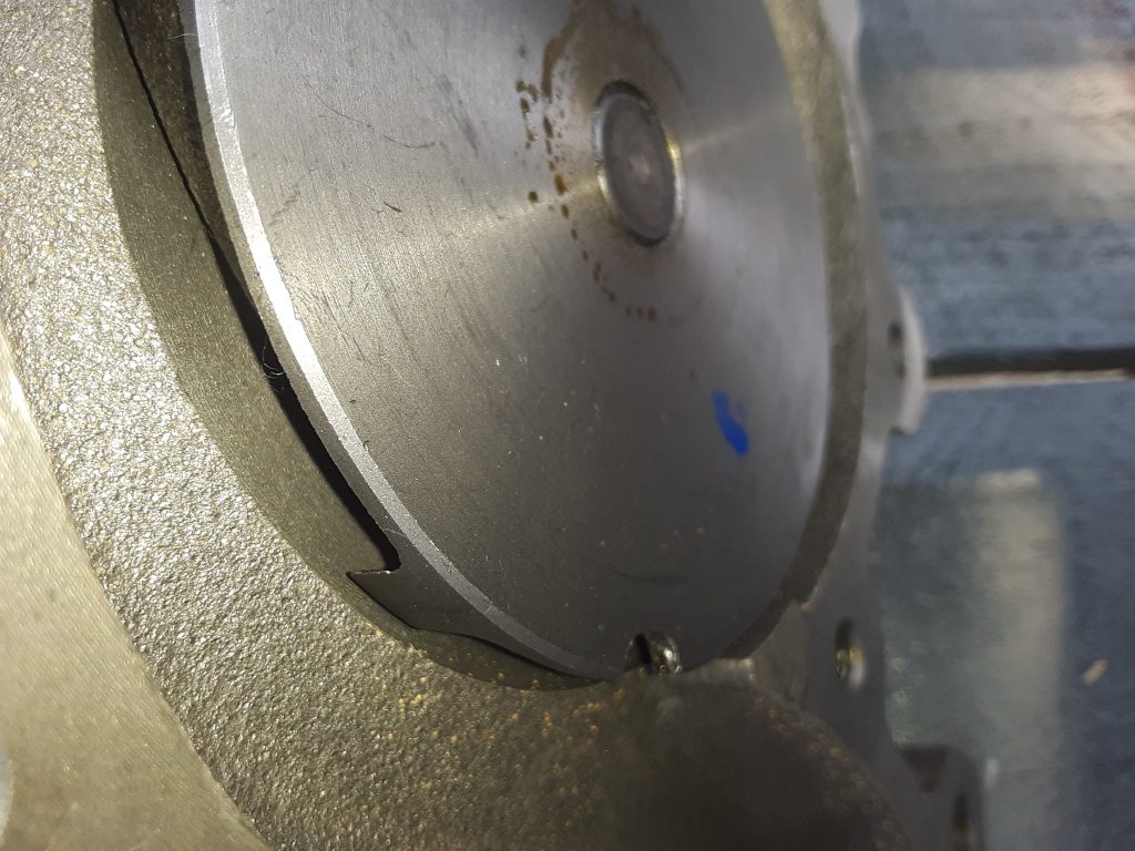
Second, as discussed in the earlier posting, we needed to confirm that the rotation of the pump was correct. (V-belt applications use a rotor that rotates in the same direction as the engine, while serpentine belt drives require an impeller designed to work in the opposite direction).
Upon visual confirmation, the impeller vanes are the same.
After confirming the AC Delco 252-611 was a proper replacement, we painted the water pump with a glossy engine enamel to match the original pump. In painting a water pump be sure to not paint the face where the pulley mounts, the bearing (as paint can damage the seal), the ports where the fittings go (to ensure proper sealing), and the area where the lower radiator hose mounts to the pump.
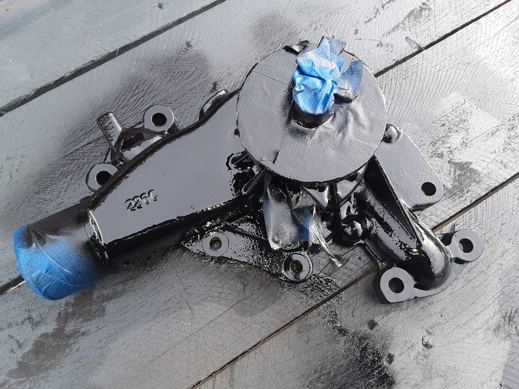
Note masking to prevent paint on areas that should not be painted. After removing the masking tape, we were ready to install the pump.
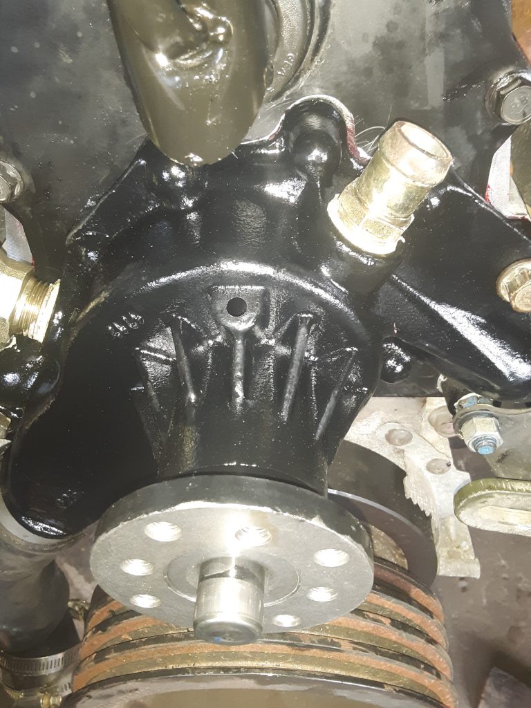
As a note, we installed all bolts holding the timing gear cover and the water pump to the timing gear cover with blue Loctite. As there are seven bolts holding the water pump installed from the inside of the timing gear cover, it is extremely important to use Loctite and torque to specifications. Should one of these bolts loosen or fall out, they fall directly into the timing gears.
Additionally, there are five bolts installed from the outside that are tapped into the water jacket. It is important to re-apply sealant on these threads to ensure engine coolant does not leak on the threads. We used Rectorseal #5, but other products will also suffice.
UPDATE: As we reviewed the drop-shipping invoice, the water pump is billed out as a GM 88926125. This application shows at least for civilian 1990 6.2L, and also corresponds with Airtex AW5008 indicated in a prior post.
During transit, one of the cooling fan blades on our powertrain sustained damage. While it would likely still be serviceable under some situations, we investigated, and ultimately replaced the part with one of Chinese manufacture.
The fan used in our unit is the same for either the 6.2 or the 6.5 NA on the v-belt application 4140-01-211-8403 [4140012118403]. We spoke with representatives of IvyWay Truck Parts https://www.ivywaychina.com/ and acquired a manufactured-in-China fan to test and review.
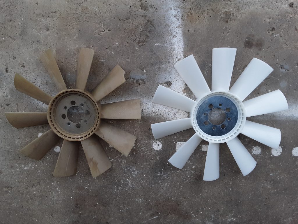
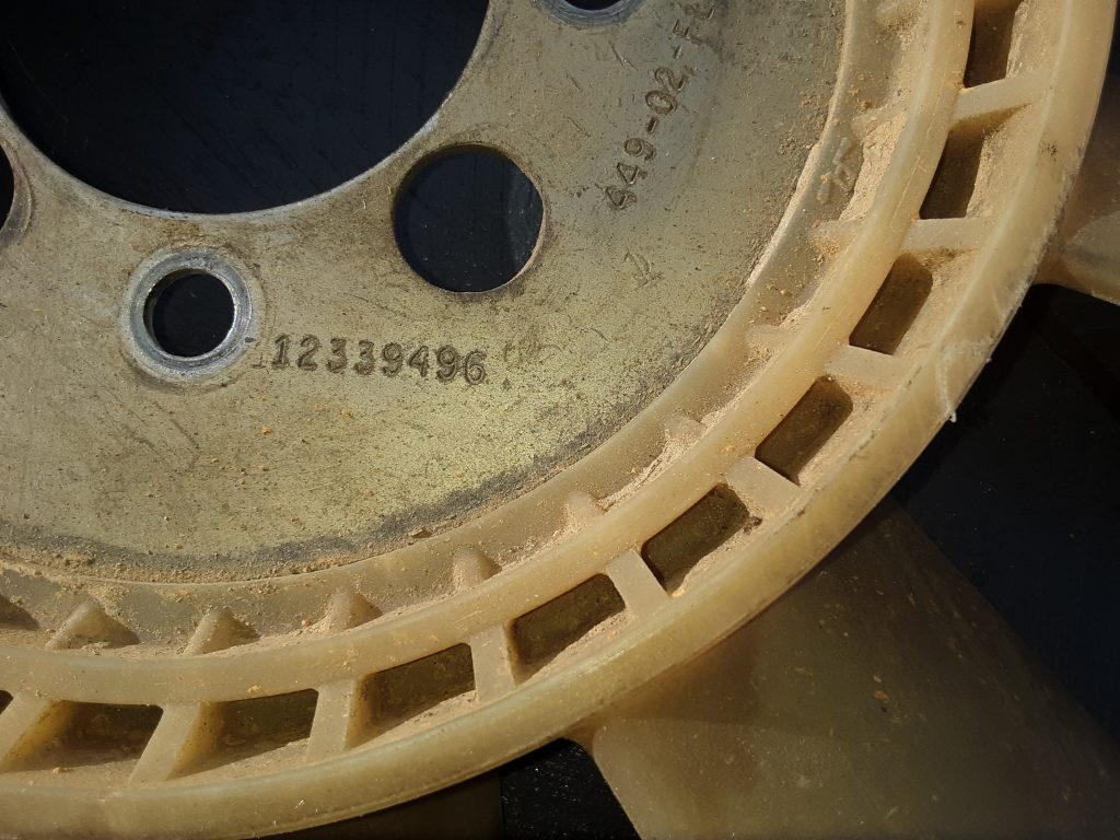
The original fan is on the left, and the Ivyway fan is on the right. (note chip missing out of blade on original fan). We went over the Ivyway fan with a caliper and could not find any difference between the two other than the Ivyway did not carry the AM General part number:
And that small gussets molded into the base of each blade. (which we determined was an improvement over the original). [Picture yet to be uploaded]
The price difference between the Ivyway and the AM General fan is a factor of about 4 times. Additionally, we feel that the gusset molded into the blades is an improvement and should add additional strength.
We will run the Ivyway fan in our Project: M1038 to determine how well it holds up and report later if we note any issues. We do feel comfortable, however, that the quality is likely on par with the original part, especially since most plastics manfacturing is done overseas anyway. (e.g. carbon fiber bike frames, YETI coolers, etc.)
At this time, we are of the opinion this HMMWV part manufactured in China is as good, or possibly superior, to the OEM part.