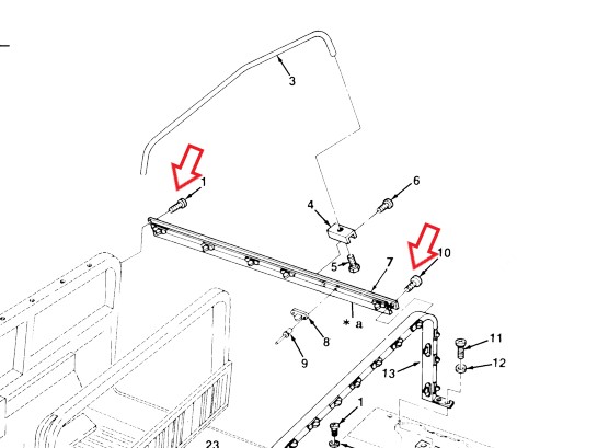
The screws at the front, middle, and rear of each rail are called out by different part numbers in the TM. The front screw (#1) 5305-01-210-6249 [5305012106249] with a manufacturer P/N of PL25D02P12 was not locatable.
The screw at the rear of the rail (#10) 5305-01-117-3396 [5305011173396] was similarly unlocatable, however we were able to locate this screw by its manufacturer P/N of NAS1635-3LE12. This is essentially a #10-32 x 3/4 screw. However, this has pre-applied locking compound. Additionally, we surmise this screw probably has a higher tensile strength than a standard 10-32 screw as it is an aircraft fastener.
As for the PL25D02P12 fastener called out for the front connection, at least one vendor (Kascar/real4wd.com) lists the NAS1635-3LE12 as an interchange. (at time of post, searching for the PL25D02P12 fastener comes up as NAS1635-3LE12) See: https://real4wd.com/store/catalog/search.aspx?keywords=PL25D02P12
In other words, we are comfortable that since both fasteners specifications are as a self-locking 10-32 x 3/4″, that use of the NAS1635-3LE12 is proper. There are apparently 50 in a box, and we have ordered 4 boxes to keep in stock.
As our shifter was frozen solid, it required use of a hydraulic press, hammer, and punch to dissasemble the shifting mechanisms. In the process, we ended up destroying both the shaft and the bushing.
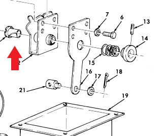
This bushing 3120-01-191-3232 [3120011913232] (indicated by red arrow) is made of thin nylon. Although after looking at it, we could have replaced it with an oilite or brass bushing, that would require machining of the shifting bracket. We then attempted to source the bushing using the NSN with no luck. However, we were able to located the part (currently available for order) from the manufacturer using the part number 10L18F. Applied Industrial Technologies carries this part available at https://www.applied.com/c-brands/c-thomson-industries/10l18f/Thomson-Nyliner-Bearing/p/101610126.
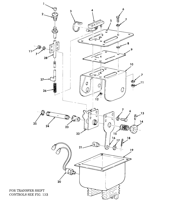
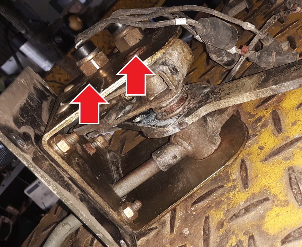
The transmission shifter in our M1038 was frozen, in that the release button could not be depressed to release the shifter. Additionally, the lever 2520-01-189-1064 [2520011891064] (Fig. 99, Item 16) was broken at the connection point. After removing the entire assembly, we noticed that this was an atypical shifter in that it had not only the safety switch 2920-01-249-3492 [2920012493492](Fig. 99, Item 20), but also a reverse light switch (not shown in diagram).
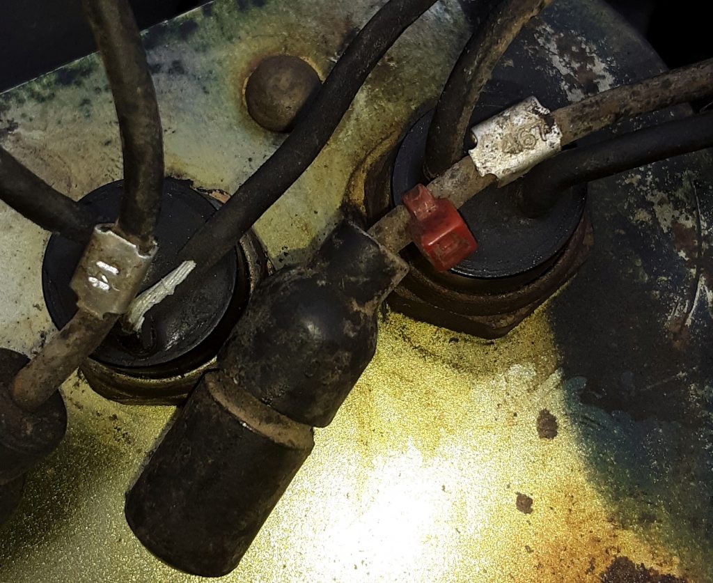
Shifter showing neutral safety switch and reverse light switch. Reverse switch is the right arrow.
It is our current understanding that the reverse light switch was used only on Marine HMMWVs, but that it is also desirable for on-road civilian use in states that require a functioning reverse light. The lead from one of the wires was 467 (whereas the neutral safety is 14). Of note, the hole for the reverse switch appears to exist in all of the housing assemblies (Fig. 99, Item 10). (See diagram). Of further note, the switch appears to be the same as the neutral safety other than there is a bushing installed to allow the smaller switch to be installed in a larger hole
From this, it appears that a reverse light switch can be installed in any of the earlier shifters. Once we identify the threaded bushing dimensions, we will post it. It seems relatively difficult to source the reverse light switch as opposed to the neutral safety switch.
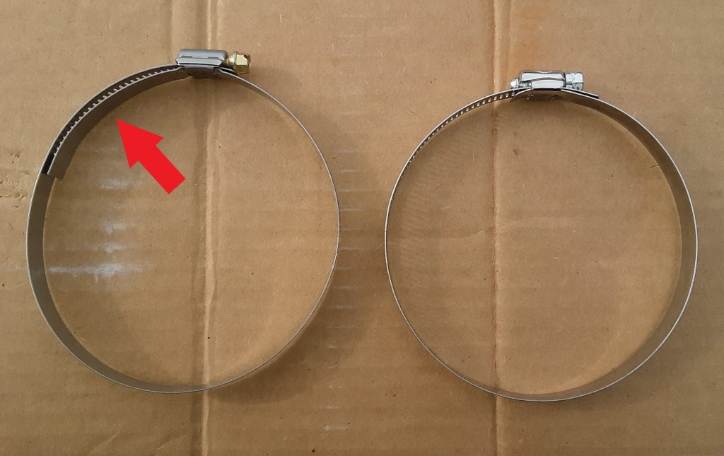
There are two primary types of “open” hose clamps. The two pictured above are SAE Size 72, which we determined is the commercial equivalent of clamp 4730-00-359-9487 [4730003599487].
On the right is the standard hose clamp. On the left is what is referred to as a “liner” hose clamp. The Red Arrow points to a shield that protects the hose from extruding through the “rack” portion of the hose clamp. Liner clamps are often called “military clamps,” but in fact, the liner is designed for clamping softer materials such as silicone hoses.
This size clamp is called out to tighten the 90 degree hose used to connect to the fording stack extension 2510-01-198-0333 [2510011980333] and to the air cleaner. (See Figure 398, Item 31).
Of interest, the standard hose clamp in Size 72 worked perfectly for the fording tube application, however the “liner” clamp was too small. In fact, the liner clamp was manufactured by Breeze, a company that is a supplier of hose clamps to the military.
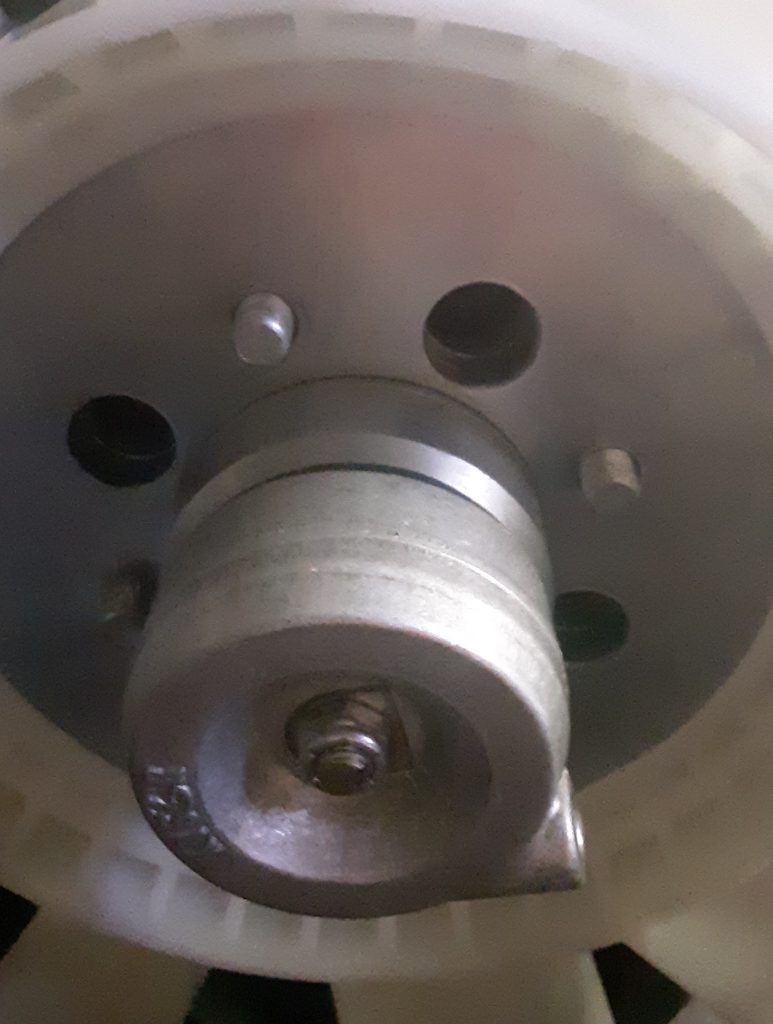
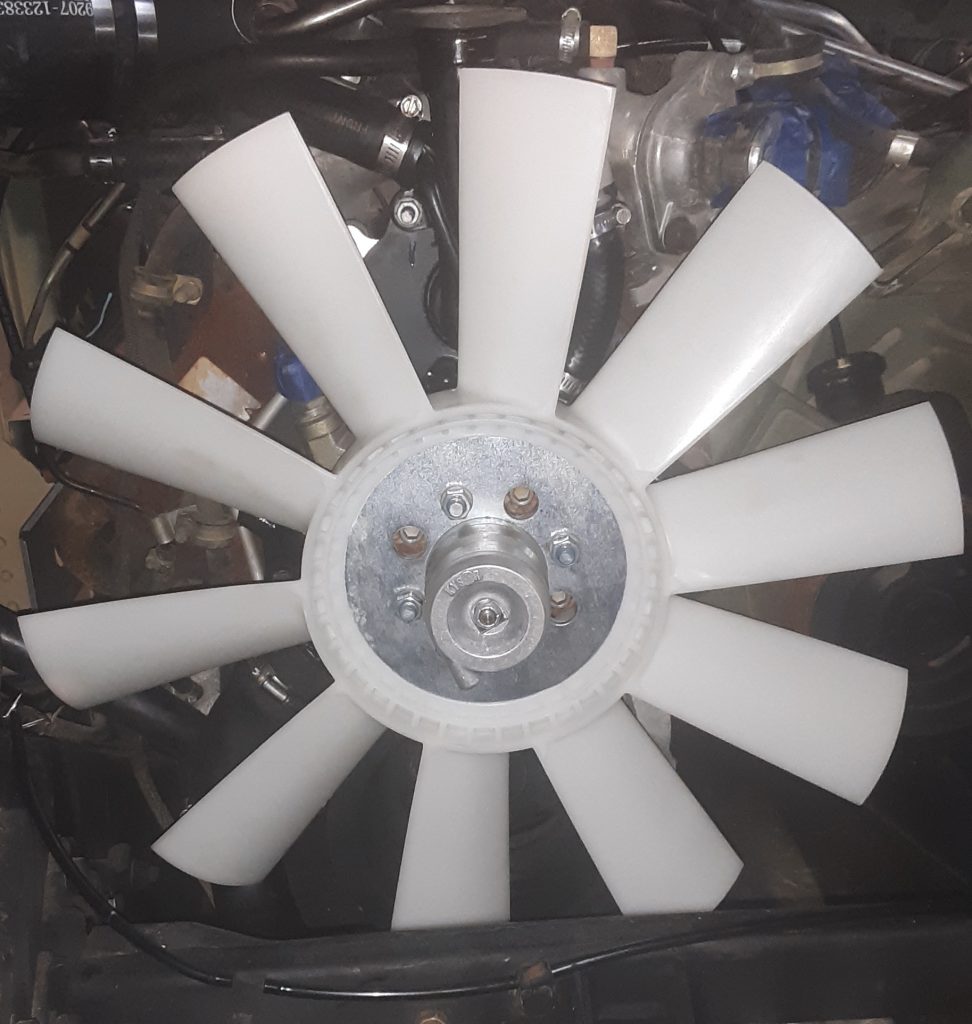
The fan used for either 6.2 or the 6.5 NA on the v-belt application is4140-01-211-8403 [4140012118403]. As discussed in this post, the quality and materials appear to be comparable to OEM. The fan itself centers on the diameter of the fan clutch. We had to dress the inside of the fan in order to install it. We do not feel this to be a flaw, but rather precise hand-fitting of the fan to the fan clutch.
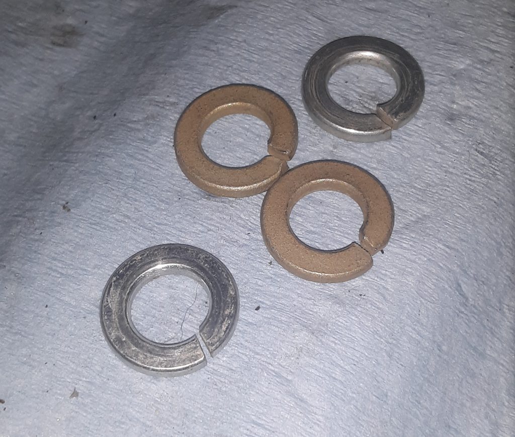
The lock washers taken off of the fan appeared to have not retained its spring-like characteristics. We believe they used Grade 5 or less washers on installation. We replaced those washers with Grade 8 (the gold ones) to ensure locking capacity. (Of note, we also used Blue Loctite as an extra safety measure).
The silver lock washers were removed from the vehicle, the gold Grade 8 ones were used to replace them. Note: there are four lock washers required, only two of each were photographed as examples.Picture of fan assembled to fan clutch.
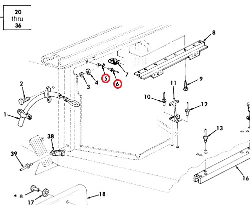
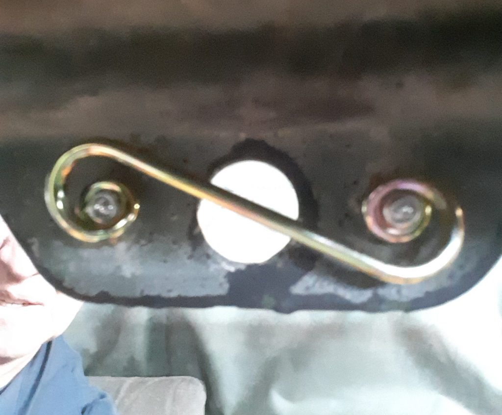
To replace the quarter turn fastener springs 5325-00-449-3001 [5325004493001] (Item 5 above), drill out the existing rivets 5320-00-083-5009 [5320000835009] (Item 6) with a 1/8″ drill bit.
These parts can be substituted as follows: First, the quarter turn spring can be substituted with Dzus or generic quarter turn fastener springs with the dimensions of spring height to latching surface .150″ to .175″ and measurements of 1-3/8″ eye to eye. Second, the rivets are simply 1/8″ diameter x 5/16″ length.
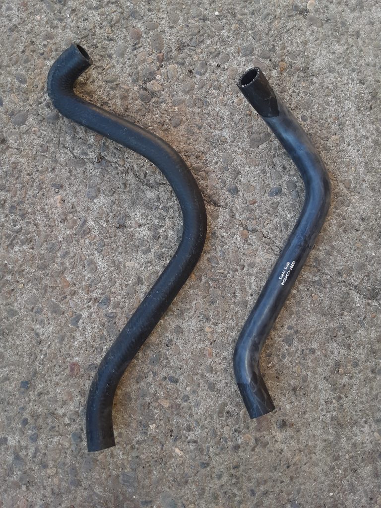
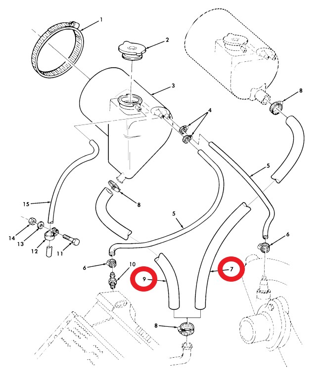
Left side, hose 4720-01-196-1636 designed for early version; Right side, hose 4720-01-360-2380
As our M1038 was an extremely early version, we assumed it would use the hose for the earlier version 4720-01-196-1636 [4720011961636] (Fig. 27, Item 7). However, we apparently had a later version tank 2930-01-256-5350 [2930012565350], so we required hose 4720-01-360-2380 [4720013602380] (Fig. 27, Item 9).
We note that we installed the hose intended for the earlier tank and could have simply cut off the excess length. However, there is a slightly different bend that gave us some concern about clearance with the radiator side shield. (After we installed the side shield, however, it was clear that cutting the earlier version hose would clear)
As we discussed in an earlier post, Dexron III is what was called for in the Transfer Case, and use of Dexron VI has led to parts failure. As discussed, our research indicates that GM continues to recommend use of Manual Transmission and Transfer Case Fluid 88861800 for the transfer case.
As the picture indicates, this fluid is also marketed as AC Delco 10-4033. We used a Lincoln suction gun to fill the 242 transfer case. We had previously drained the transfer case to ensure no contaminants were present, and used just about 2 1/2 quarts to bring the fluid to the proper level.
Although we have identified fluids being marketed as “recommended for” Dexron III applications, we chose to use GM’s recommendation as we did not want to risk loss of a transfer case. However, we will likely use a “recommended for” Dexron III (H) fluid when we fill the transmission, and bleed out the cooler and winch.
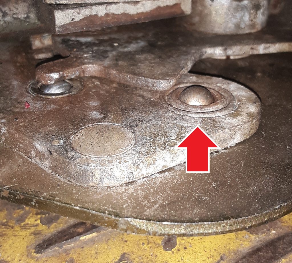
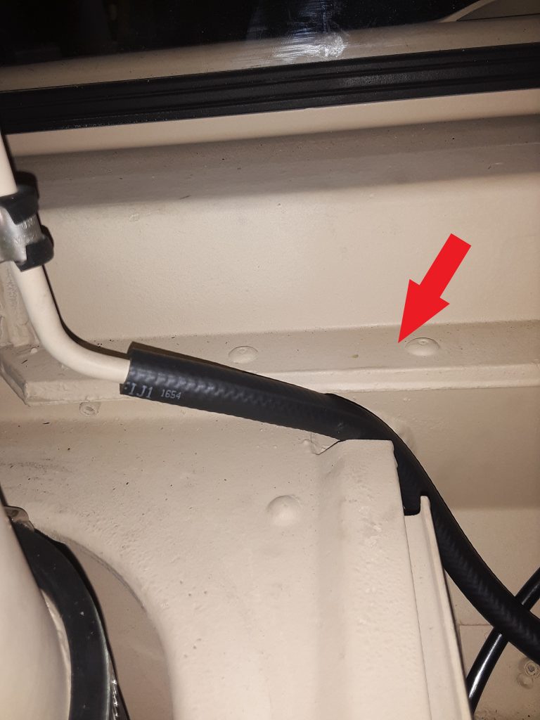
Hose is Figure 398, Item 30. (The Corbin clamp is not on the vent tube at time of photo)
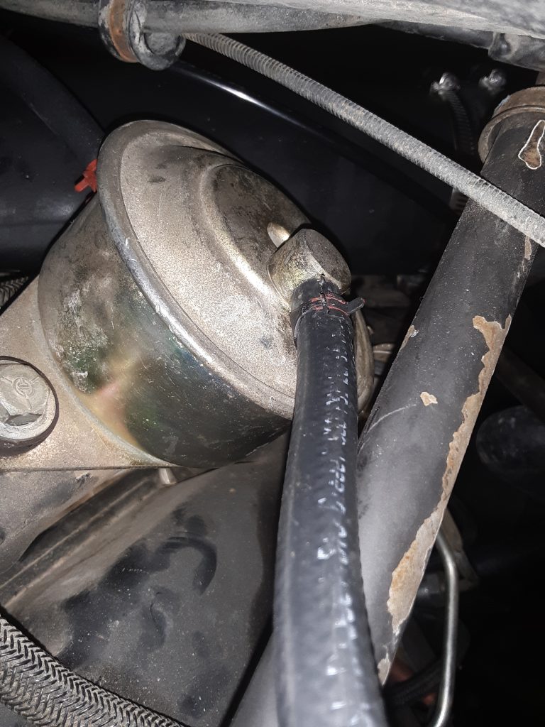
The arrow in the photo above indicates the position where the vent hose leading from the fuel tank vent line filter 2910-01-210-5872 [2910012105872] (behind the surge tank) is to be placed for clearance when the hood is closed. Note a Corbin style clamp 4730-00-954-1251 [4730009541251] needs to be placed on the hose ends both where the hose attaches to the tube and to the filter.
The callout for this hose is for an 11″ length of CPR104420-2 (replaceable with 3/8″ air brake tubing, such as Eaton Synflex®). We instead replaced this with 1/4″ SAE J30R9 hose (which we consider a modern and equal substitute for RB1450-1-4IDX1-20D).
Our reasoning for using hose instead of tubing is based on a couple factors: First, it is called out as RB1450-1-4IDx1-20D (or equivalent) to connect the fuel tank vent line to the fuel vent line filter (See Figure 18, Item 6). We are of the opinion the hose leaving the vent line filter should be the same as the hose entering the filter, and that indication of tubing may be an error in the TM. Second, use of air brake tubing essentially requires a heat gun to soften the tubing enough to slide over the tube on the stack and bead on the filter itself. Although this can be accomplished, should field repairs be necessary, it essentially requires cutting the tubing, where the hose can be easily removed by loosening the Corbin clamps.
Note: the drawing indicating the vent line hose appears to be the same as the hose entering the vent, and does not appear to be tubing. Although this may be based simply on the artist, we are of the opinion that the hose leaving the vent should be the same as the hose entering the vent.
We note the installation instructions for the DWF kit also indicates the CPR104420-2. See http://www.hummerknowledgebase.com/driving/dwf.html (at Image 3), where is specifically calls out an 11″ length. (We do, however, note this document is extremely dated, as it calls out for use of Dexron II at Image 5). Dexron II was long ago deprecated: In 1993, GM released new Dexron-III fluid (GM Spec GM6417M and later GMN10055). As noted above, we believe the J30R9 hose is made from material superior to what was available during original engineering of the HMMWV. and stand by our recommendation to instead use J30R9 hose.
Although we have no way of knowing at this time, there may have been a UV (sun) resistance issue where the engineers preferred the air brake tubing over the hose for that reason. It may well be that the CPR104420-2 tubing has a greater resistance to breakdown that the RB1450-1-4IDx1-20D hose. However, we are around 30-some years since the original design, and materials have changed. We will monitor the J30R9 hose to determine if it exhibits any undesirable weathering characteristics.
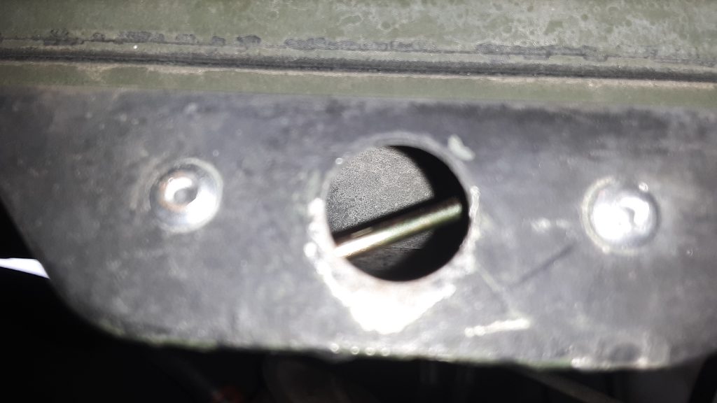
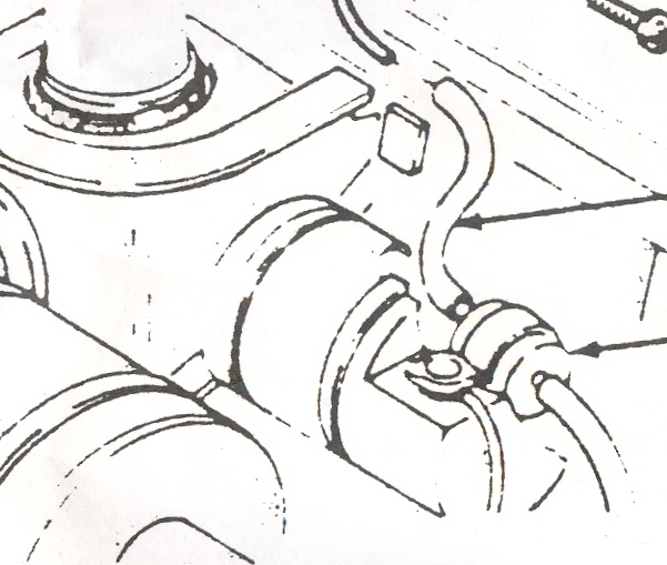
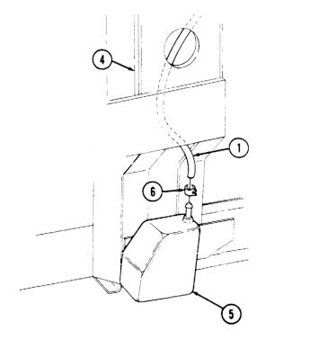
The above figure appears as if it is a straightforward task to insert the cup sensor to CDR vent hose (No. 1 in picture).
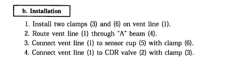
In fact, even the instructions, Sec. 12-13 (TM 9-2320-280-3) makes it appear that you simply have to “route vent line through “A” beam.”
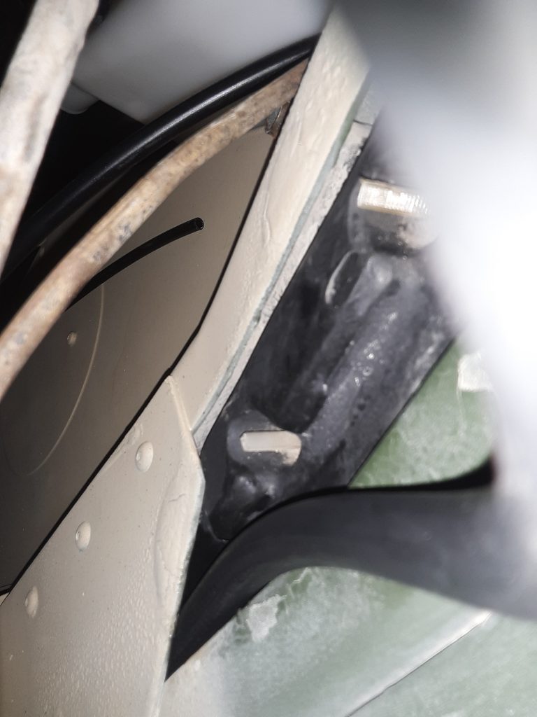
It truly is not a simple task. Ours being a Marine unit seems to be lacking in most of the insulation. It did, however, have the insulation installed inside the “A” beam. We erroneously made the assumption that since our HMMWV was originally equipped with the fording system, it should be as simple as the manual indicated. We spent several hours trying to thread the hose from both the top and the bottom with no success. The hose would consistently stop around the halfway point.
After running the lift up and down a number of times, we decided to see whether we could “fish” a piece of 3/8″ air brake tubing through the pillar. Although it took considerable effort, we were able to push the brake tubing completely through. We then connected the tubing to the hose with a 1/4″ hose barb and attempted pulling the hose through. That method failed on several tries.
We were ultimately successful using pure silicone (silicone gel for waterproofing / rubber boots, etc., not RTV) to lube the end of the hose and about half way up. The hose easily slid through. We suspect that there was just too much friction where the hose was somewhat pressed against the insulation.
Being that we have a crate of circa 1960 Dow Corning military surplus silicone, there was no cost. However, in the event you aren’t oversupplied with silicone gel, we strongly suspect that tire bead lubricant or even dishwashing soap would also serve as well.
View of CDR to Sensor Cup vent line as it enters top of RH “A” beamView of CDR to Sensor Cup vent line connected to CDR. Note routing of vent line across top of transmission dip stick tube. (this tube will be replaced with a DWF tube)