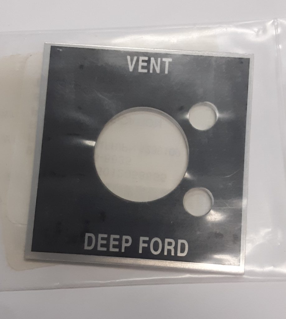
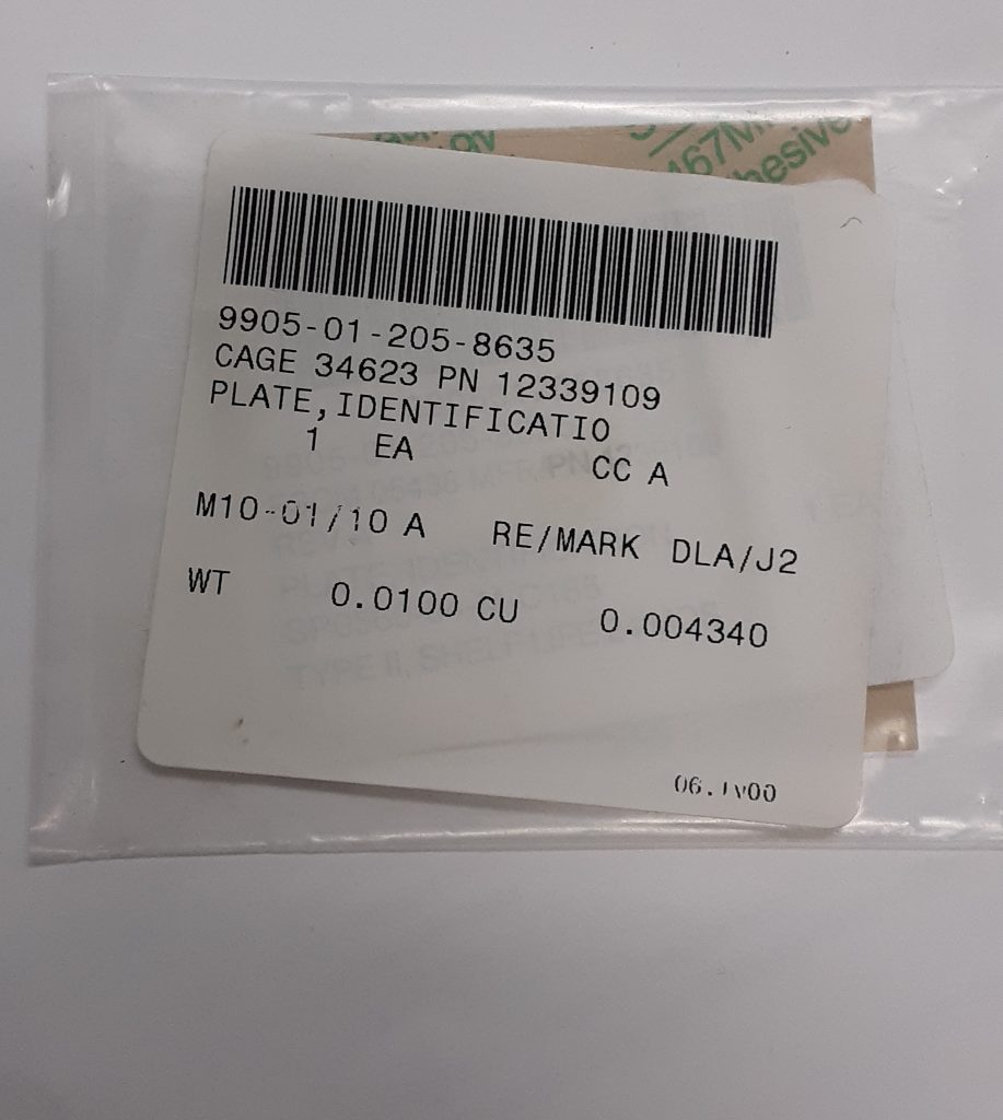
Although not necessary for a serviceable vehicle, generally replacing a worn or missing instruction plate is a worthwhile endeavor. The left picture shows the face of the plate that goes over the fording valve handle. The right picture shows the NSN of 9905-01-205-8635 [9905012058635]. It also appears to have an AM General P/N of 12339109
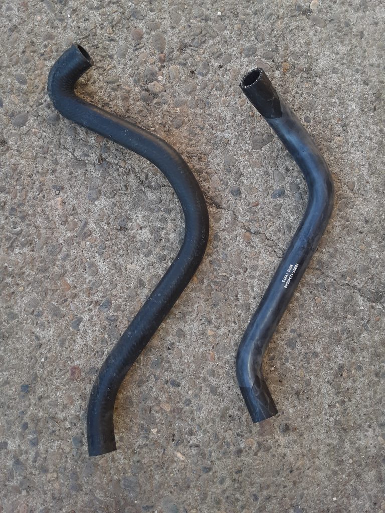
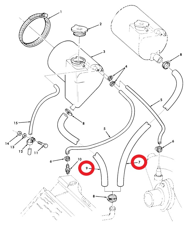
Left side, hose 4720-01-196-1636 designed for early version; Right side, hose 4720-01-360-2380
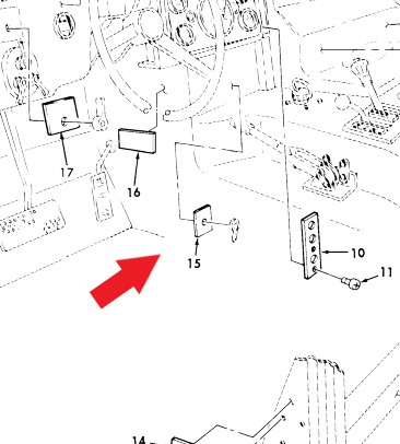
As our M1038 was an extremely early version, we assumed it would use the hose for the earlier version 4720-01-196-1636 [4720011961636] (Fig. 27, Item 7). However, we apparently had a later version tank 2930-01-256-5350 [2930012565350], so we required hose 4720-01-360-2380 [4720013602380] (Fig. 27, Item 9).
We note that we installed the hose intended for the earlier tank and could have simply cut off the excess length. However, there is a slightly different bend that gave us some concern about clearance with the radiator side shield. (After we installed the side shield, however, it was clear that cutting the earlier version hose would clear)
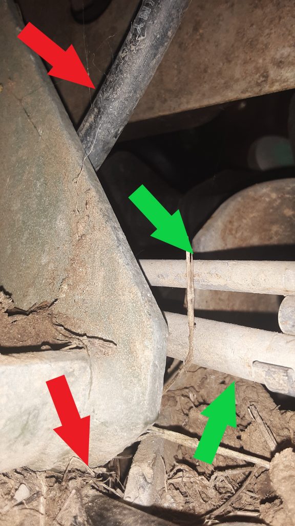
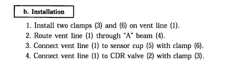
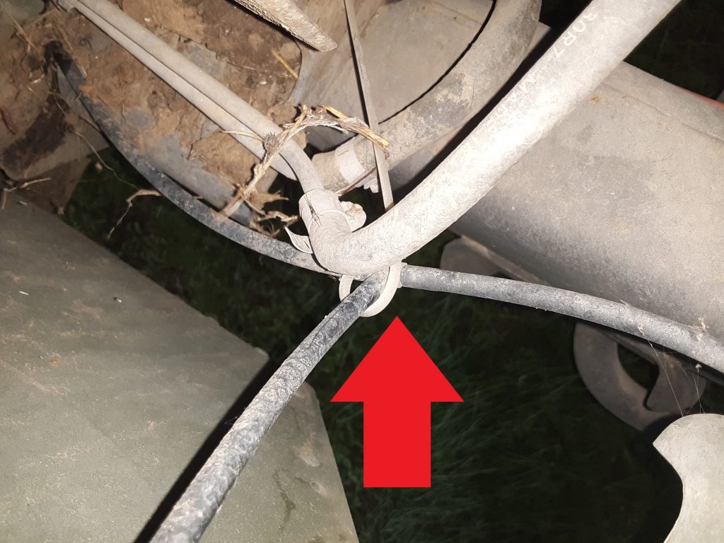
We were unable to locate specifically where the vent line from the rear routes around the right motor mount. We crawled under one of the M998s on the ranch and were able to snake a cell phone up to take some pictures.
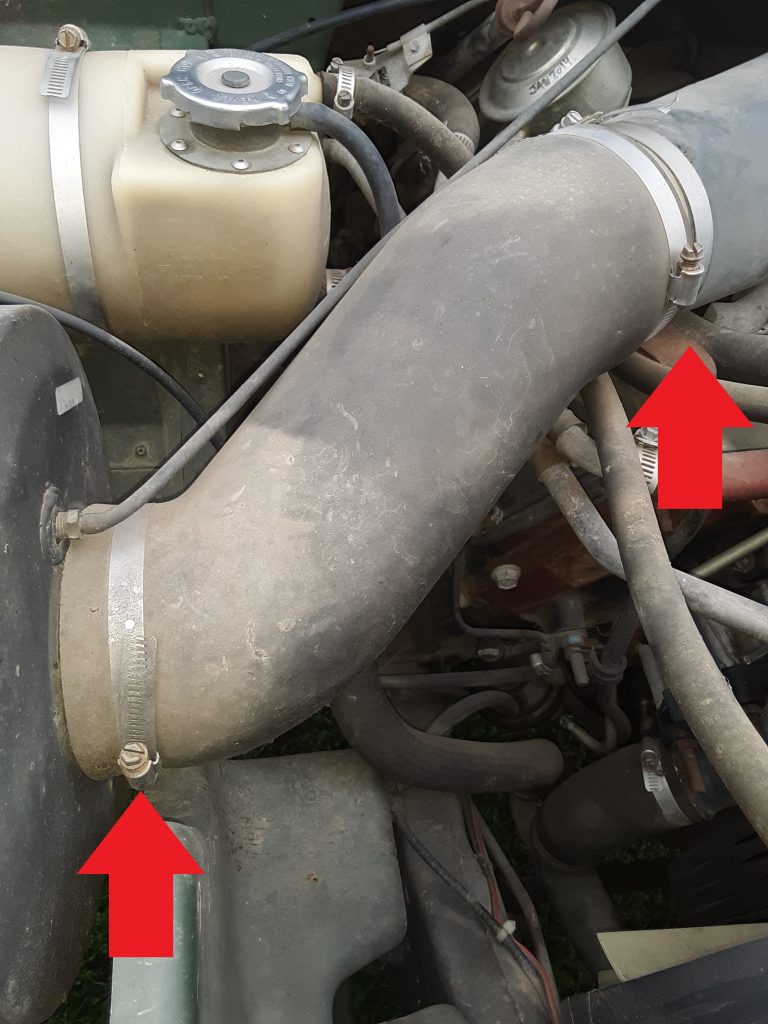
Lower Red Arrow – Vent line from rear of vehicle; Upper Red Arrow – Fuel Tank Vent line to filter/intake stack; Lower Green Arrow – Fuel line from tank; Upper Green Arrow – Return line to tank.
As best as we can tell, there is simply no cushion clamp to mount the vent line, and it lays across the frame between the motor mount and the body mount (just under the mount flange riveted to the body).
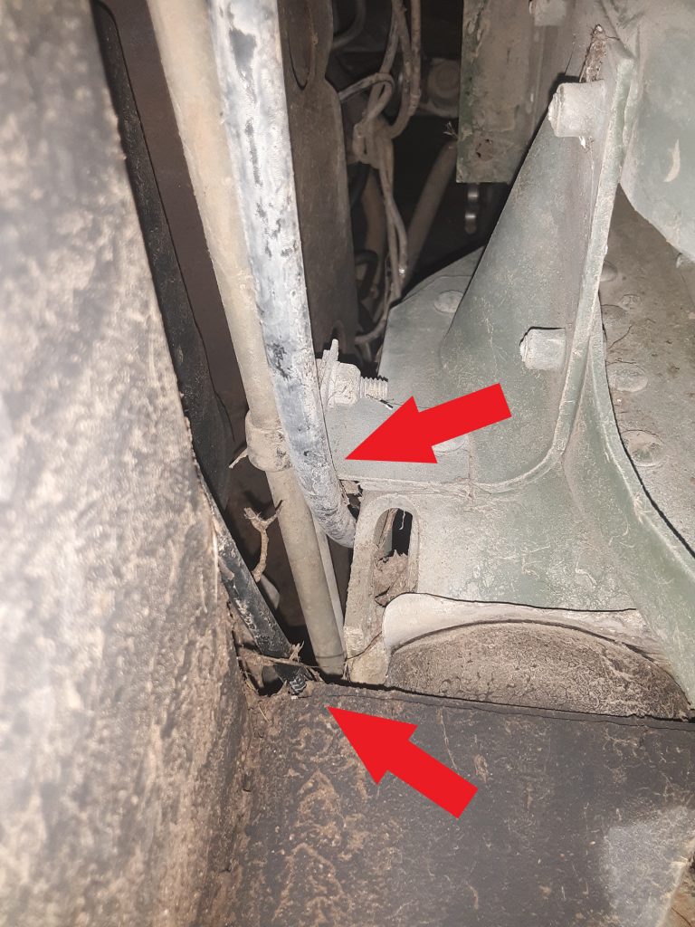
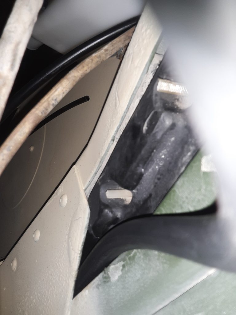
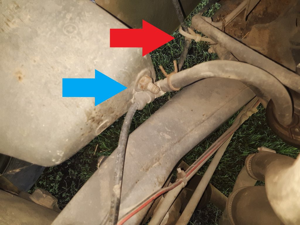
Lower Red Arrow – rear vent line; Upper Red Arrow – fuel tank vent line
Viewed from the rear of the RH front body mount, it is clear that the rear vent line leaves the top of the frame to lay across the frame support for the body mount. Also visible is the fuel tank vent arcing upward underneath the fuel line support and cushion clamps.
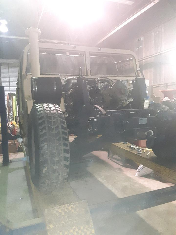
The bay lights unintentionally caused this picture to have a “filter” effect, which was not desired. Most of the work from the last update picture has been connections and hookups on the engine and powertrain.
Externally, the air filtration system and fording intake stack have been installed. Additionally, all of the axle, transmission, and transfer case vents have been connected, as well as the fording valve, CDR and power steering. The only plumbing left to install is the fuel and transmission cooling lines.
We believe we are still on target for a February painting schedule.
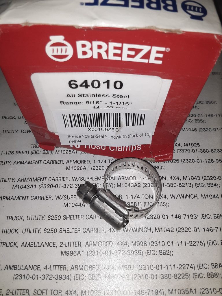
As in previous posts, we have identified hose clamp sizes and their commercial interchange numbers. For the heater hoses, we have confirmed that SAE 10 is the correct size. Above are Breeze brand clamps, and Breeze has a history of manufacturing hose clamps for military use.
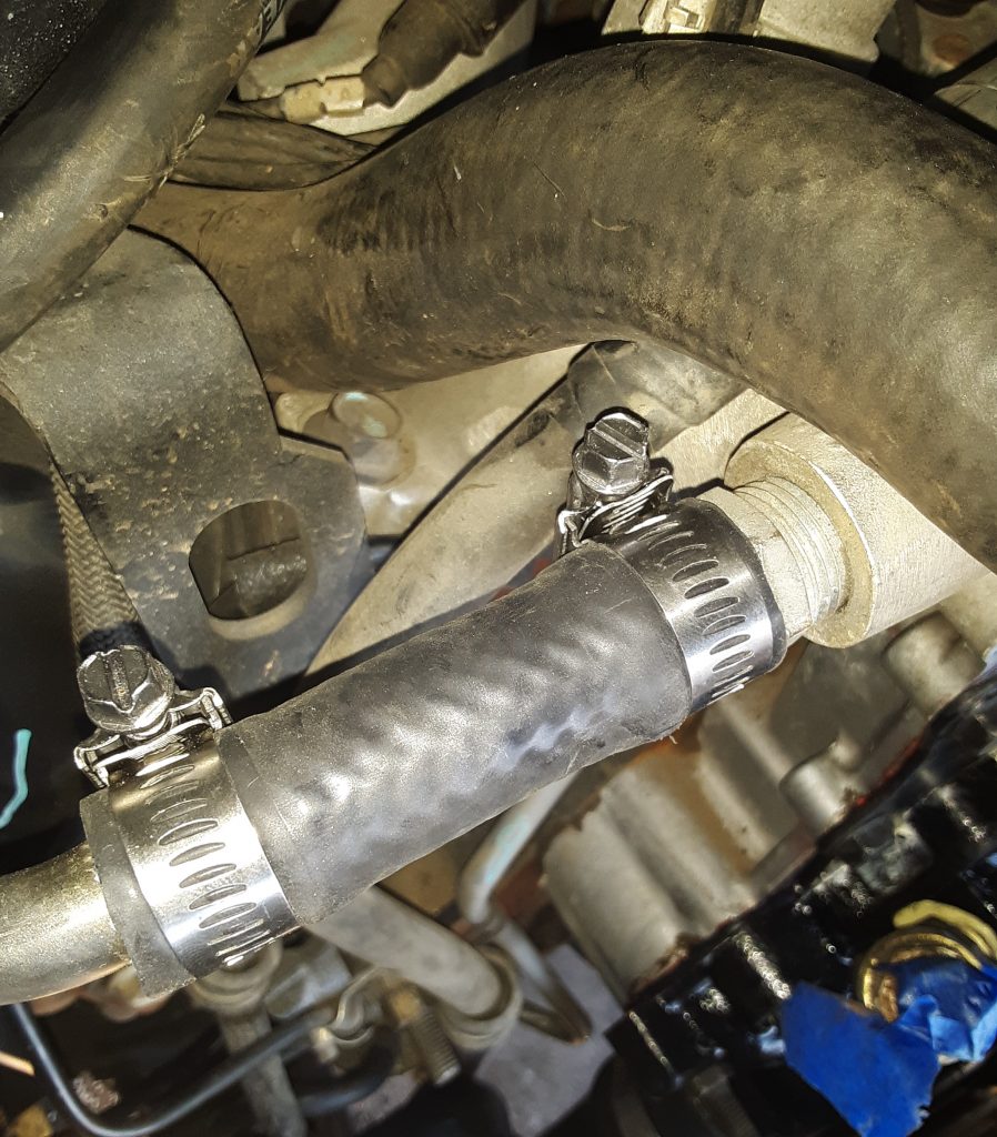
SAE Size 10 hose clamps installed on manifold to heater hose pipe.
As we discussed in an earlier post, Dexron III is what was called for in the Transfer Case, and use of Dexron VI has led to parts failure. As discussed, our research indicates that GM continues to recommend use of Manual Transmission and Transfer Case Fluid 88861800 for the transfer case.
As the picture indicates, this fluid is also marketed as AC Delco 10-4033. We used a Lincoln suction gun to fill the 242 transfer case. We had previously drained the transfer case to ensure no contaminants were present, and used just about 2 1/2 quarts to bring the fluid to the proper level.
Although we have identified fluids being marketed as “recommended for” Dexron III applications, we chose to use GM’s recommendation as we did not want to risk loss of a transfer case. However, we will likely use a “recommended for” Dexron III (H) fluid when we fill the transmission, and bleed out the cooler and winch.
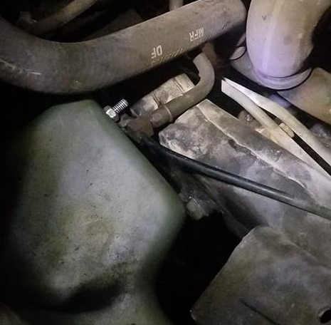
Hose is Figure 398, Item 30. (The Corbin clamp is not on the vent tube at time of photo)
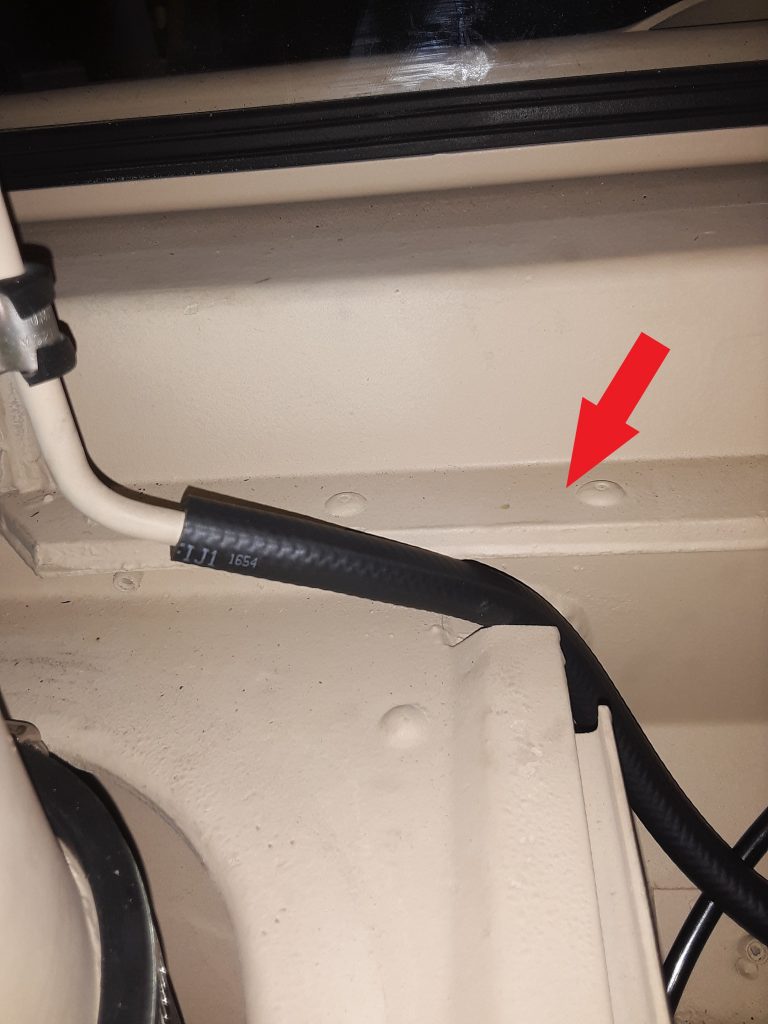
The arrow in the photo above indicates the position where the vent hose leading from the fuel tank vent line filter 2910-01-210-5872 [2910012105872] (behind the surge tank) is to be placed for clearance when the hood is closed. Note a Corbin style clamp 4730-00-954-1251 [4730009541251] needs to be placed on the hose ends both where the hose attaches to the tube and to the filter.
The callout for this hose is for an 11″ length of CPR104420-2 (replaceable with 3/8″ air brake tubing, such as Eaton Synflex®). We instead replaced this with 1/4″ SAE J30R9 hose (which we consider a modern and equal substitute for RB1450-1-4IDX1-20D).
Our reasoning for using hose instead of tubing is based on a couple factors: First, it is called out as RB1450-1-4IDx1-20D (or equivalent) to connect the fuel tank vent line to the fuel vent line filter (See Figure 18, Item 6). We are of the opinion the hose leaving the vent line filter should be the same as the hose entering the filter, and that indication of tubing may be an error in the TM. Second, use of air brake tubing essentially requires a heat gun to soften the tubing enough to slide over the tube on the stack and bead on the filter itself. Although this can be accomplished, should field repairs be necessary, it essentially requires cutting the tubing, where the hose can be easily removed by loosening the Corbin clamps.
Note: the drawing indicating the vent line hose appears to be the same as the hose entering the vent, and does not appear to be tubing. Although this may be based simply on the artist, we are of the opinion that the hose leaving the vent should be the same as the hose entering the vent.
We note the installation instructions for the DWF kit also indicates the CPR104420-2. See http://www.hummerknowledgebase.com/driving/dwf.html (at Image 3), where is specifically calls out an 11″ length. (We do, however, note this document is extremely dated, as it calls out for use of Dexron II at Image 5). Dexron II was long ago deprecated: In 1993, GM released new Dexron-III fluid (GM Spec GM6417M and later GMN10055). As noted above, we believe the J30R9 hose is made from material superior to what was available during original engineering of the HMMWV. and stand by our recommendation to instead use J30R9 hose.
Although we have no way of knowing at this time, there may have been a UV (sun) resistance issue where the engineers preferred the air brake tubing over the hose for that reason. It may well be that the CPR104420-2 tubing has a greater resistance to breakdown that the RB1450-1-4IDx1-20D hose. However, we are around 30-some years since the original design, and materials have changed. We will monitor the J30R9 hose to determine if it exhibits any undesirable weathering characteristics.
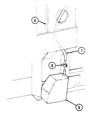
The above figure appears as if it is a straightforward task to insert the cup sensor to CDR vent hose (No. 1 in picture).
In fact, even the instructions, Sec. 12-13 (TM 9-2320-280-3) makes it appear that you simply have to “route vent line through “A” beam.”
It truly is not a simple task. Ours being a Marine unit seems to be lacking in most of the insulation. It did, however, have the insulation installed inside the “A” beam. We erroneously made the assumption that since our HMMWV was originally equipped with the fording system, it should be as simple as the manual indicated. We spent several hours trying to thread the hose from both the top and the bottom with no success. The hose would consistently stop around the halfway point.
After running the lift up and down a number of times, we decided to see whether we could “fish” a piece of 3/8″ air brake tubing through the pillar. Although it took considerable effort, we were able to push the brake tubing completely through. We then connected the tubing to the hose with a 1/4″ hose barb and attempted pulling the hose through. That method failed on several tries.
We were ultimately successful using pure silicone (silicone gel for waterproofing / rubber boots, etc., not RTV) to lube the end of the hose and about half way up. The hose easily slid through. We suspect that there was just too much friction where the hose was somewhat pressed against the insulation.
Being that we have a crate of circa 1960 Dow Corning military surplus silicone, there was no cost. However, in the event you aren’t oversupplied with silicone gel, we strongly suspect that tire bead lubricant or even dishwashing soap would also serve as well.
View of CDR to Sensor Cup vent line as it enters top of RH “A” beamView of CDR to Sensor Cup vent line connected to CDR. Note routing of vent line across top of transmission dip stick tube. (this tube will be replaced with a DWF tube)
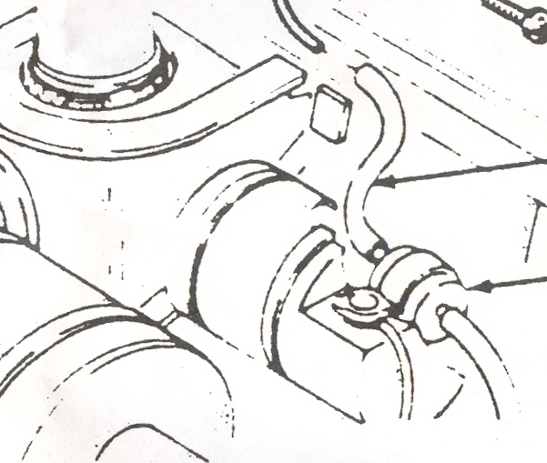
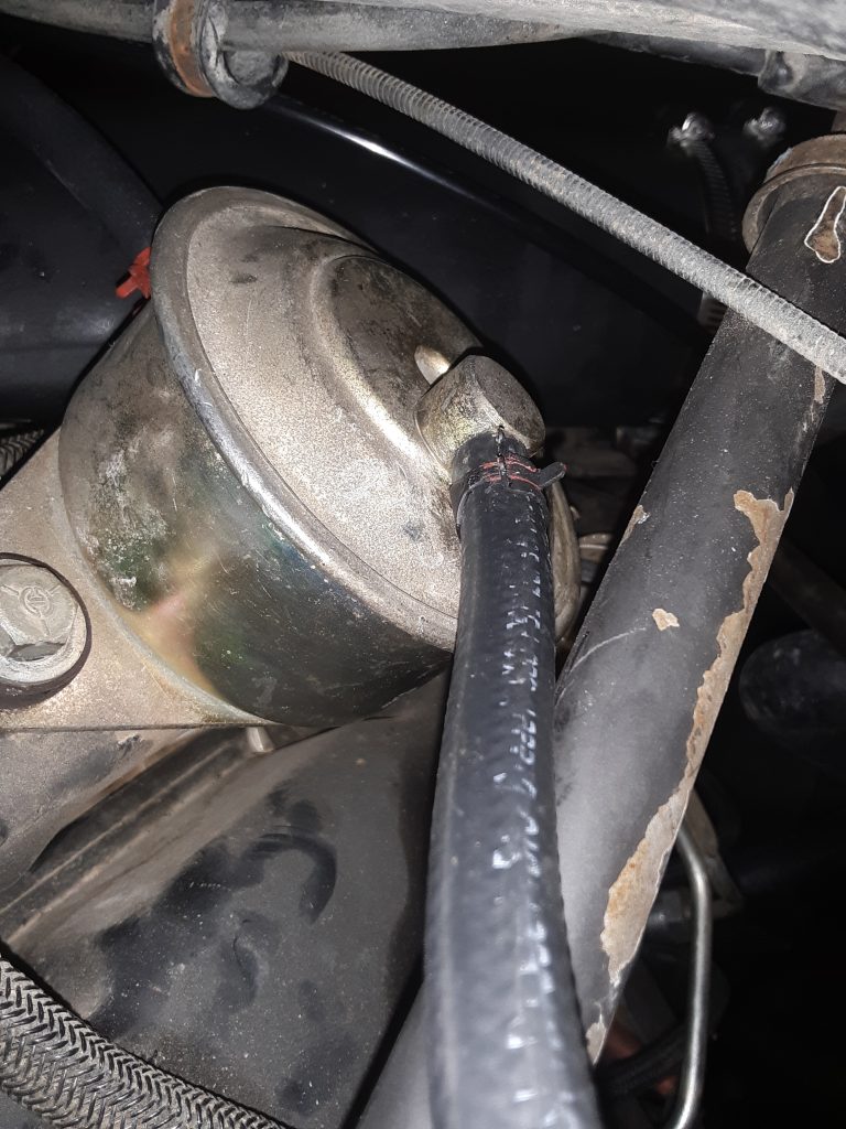
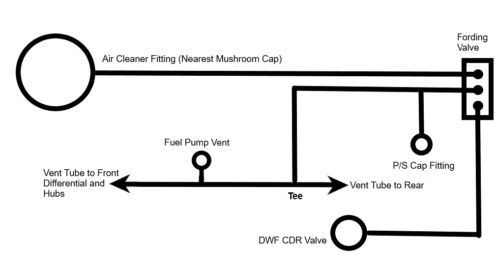
In the above diagram, a section of RB1450-1-4IDX1-20D hose (or suitable substitute such as 1/4″ SAE J30R9) goes from the bottom fitting on the fording valve to the DWF CDR valve. A section of CPR104420-1 (or suitable substitute such as Synflex® 1/4″ air brake tubing) runs from the middle port of the fording valve to a tee (where it connects to the power steering cap) and to another tee located in the vent line running along the top of the RH frame rail. The picture below shows where this tee is located
Arrow indicates “tee” where vent line from the middle port of the fording valve connects
Note above picture is of a M998 without DWF. Lacking DWF capability, this line vents directly to the air cleaner at the fitting nearest the mushroom cap. When a DWF kit is installed, this line from the air cleaner is rerouted to the upper fitting of the fording valve, and this tee becomes connected (through a new line which includes a new tee to the power steering cap) to the middle port of the fording valve.
Red arrow indicates the “tee” where a non-DWF HMMWV connects to the air cleaner, and on a DWF HMMWV the line leading from the middle port of the fording valve is attached. Blue arrow indicates the “tee” where the vent from the fuel pump connects to the vent line.
After completing this post, we located a copy of instructions for installing a DWF kit at:http://www.hummerknowledgebase.com/driving/dwf.htmlThese instructions are less than clear. However, they may provide additional information regarding Deep Water Fording equipment.
Update 1/14/2018: As seen in the picture below, the cushion clamp is placed to the rear of the tee (which corresponds with the parts manual exploded view). As of this time, we do not believe it to be crucial whether the cushion clamp is forward or behind the fuel pump vent tee. What it perhaps more crucial is the existence of the cushion clamp and that it is properly tightened.
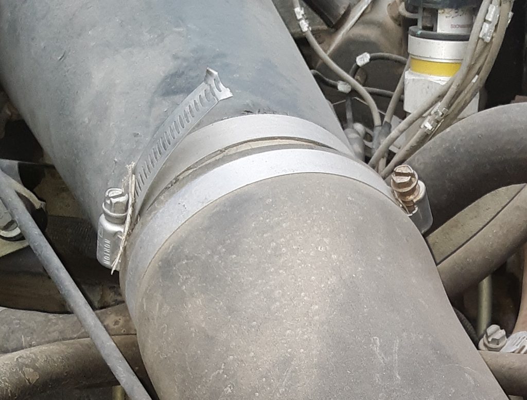
Arrows indicating locations of three hose clamps 4730-01-189-0871
Based on the call-out from the parts manual, the three hose clamps indicated below are 4730-01-189-0871 [4730011890871] or manufacturer number H68SS. Upon our research, these part numbers cross over to an SAE 68 hose clamp. Unfortunately, while size 68 clamps can be located, they are not generally commercially available. The standard (and readily available) sizes are either SAE 64 or SAE 72. We ordered both.
As it turned out (and we will post a picture later), SAE 64 is the perfect size for these three locations. We have noted that the specifications almost always call out a hose clamp considerably longer than necessary, and often leaving too much of a “tail” to grab debris, bend, and cut hands. (See photo below).
M998 Air Cleaner hose clamp showing excessive “tail” when called out part used
This hose clamp was unmodified and as received from the military. Based on what we could tell, this was a SAE 68 hose clamp.
We ordered the SAE 72 hose clamps to interchange for the clamps called out 4730-00-359-9487 [4730003599487] for use on the fording elbow 4720-01-194-5338 [4720011945338]. Although we have not yet installed these clamps, we predict they will have a considerable tail. However, those hose clamps are (for the most part) not quite as visible. On visual inspection, it appears that the SAE 68 (and possibly SAE 64) clamps may also be appropriate at that location. We will update should this information be found incorrect.