Update: Water Pump Interchange

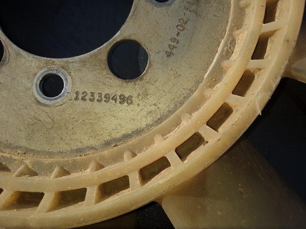
As discussed in an earlier posting, we needed to replace the water pump on our 1038, and chose to use an AC Delco 252-611 as a replacement. Once the water pump arrived, we first inspected the external housing to determine that it was dimensionally the same as the damaged pump, and found that it was virtually identical to 23500085.

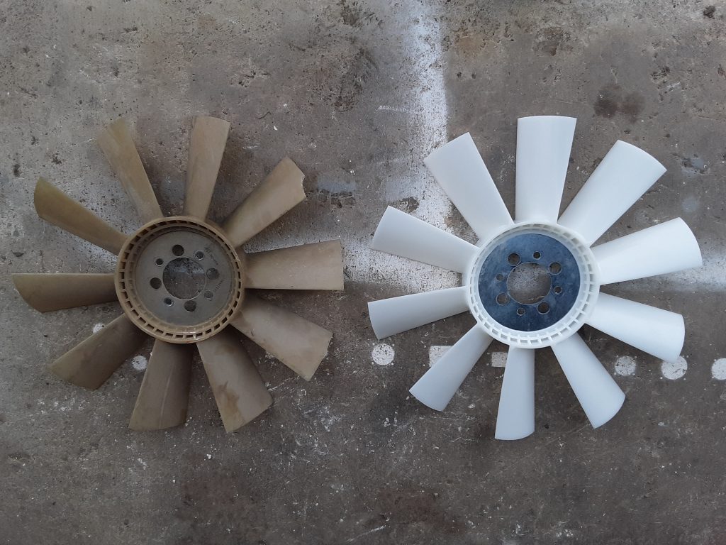
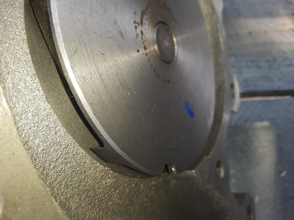
Second, as discussed in the earlier posting, we needed to confirm that the rotation of the pump was correct. (V-belt applications use a rotor that rotates in the same direction as the engine, while serpentine belt drives require an impeller designed to work in the opposite direction).

6.5 NA Original Water Pump P/N 23500085 (v-belt application)

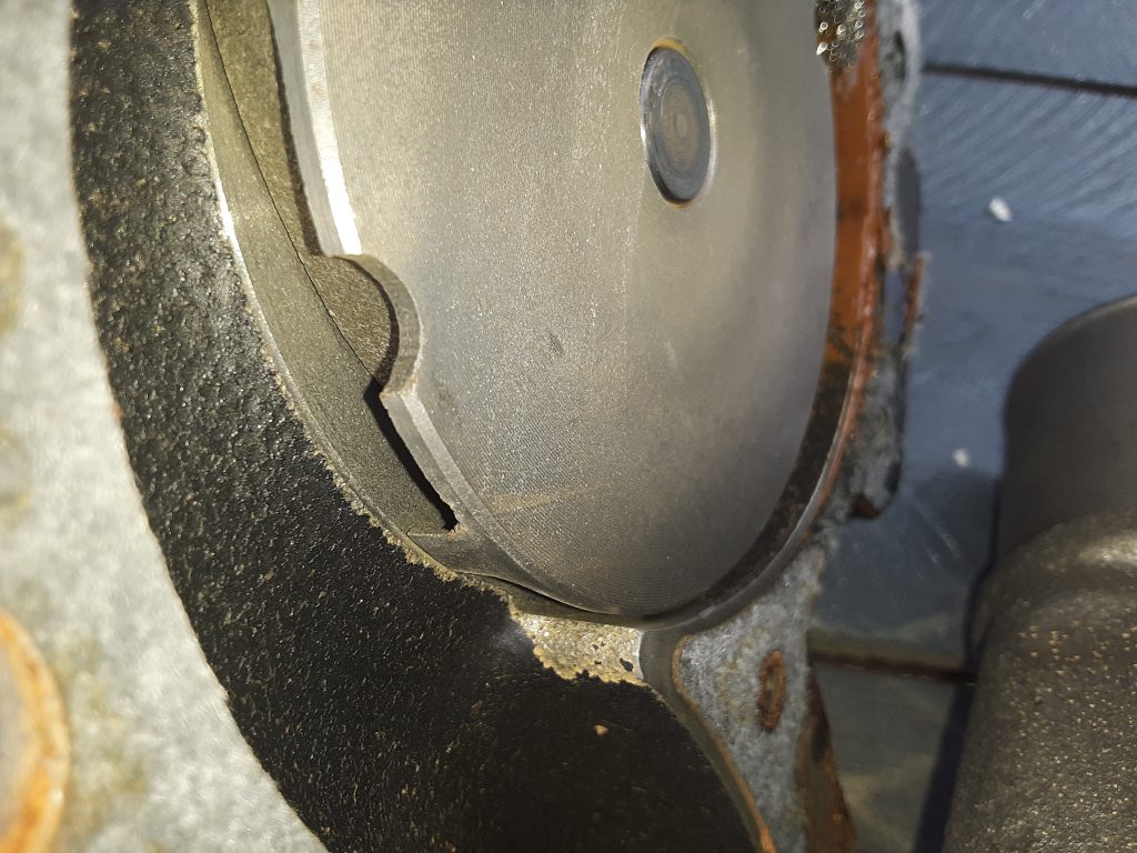
Upon visual confirmation, the impeller vanes are the same.

Replacement Water Pump AC Delco 252-611 (v-belt application)

After confirming the AC Delco 252-611 was a proper replacement, we painted the water pump with a glossy engine enamel to match the original pump. In painting a water pump be sure to not paint the face where the pulley mounts, the bearing (as paint can damage the seal), the ports where the fittings go (to ensure proper sealing), and the area where the lower radiator hose mounts to the pump.

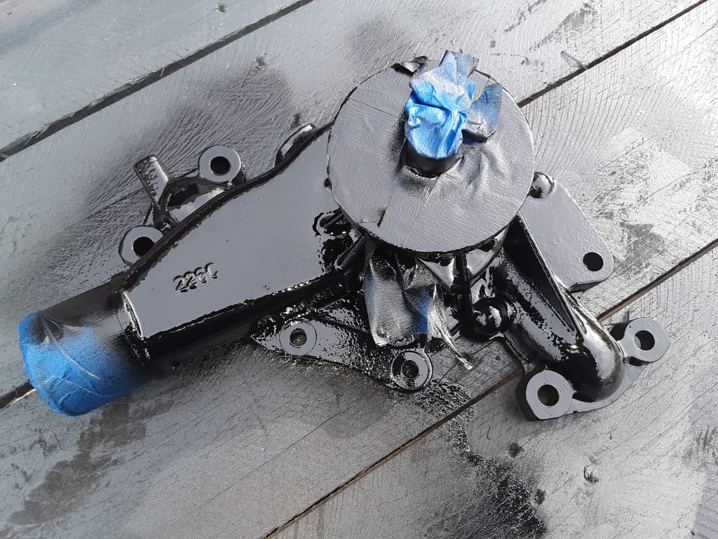
Note masking to prevent paint on areas that should not be painted. After removing the masking tape, we were ready to install the pump.

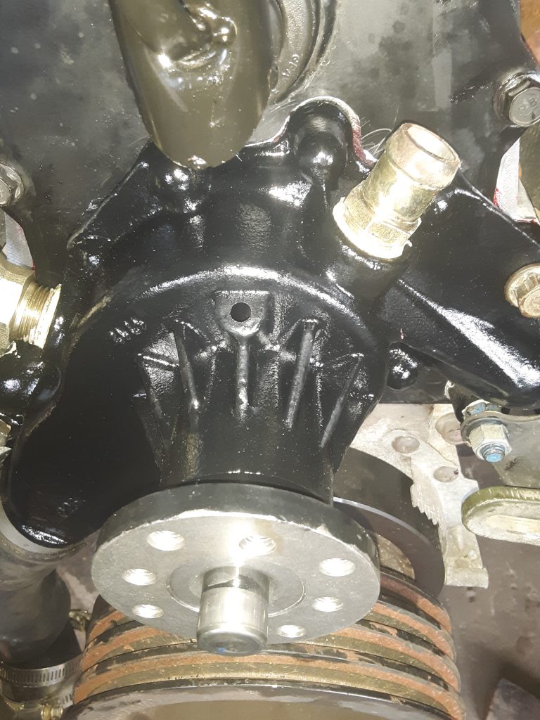
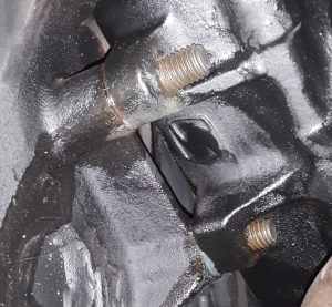
As a note, we installed all bolts holding the timing gear cover and the water pump to the timing gear cover with blue Loctite. As there are seven bolts holding the water pump installed from the inside of the timing gear cover, it is extremely important to use Loctite and torque to specifications. Should one of these bolts loosen or fall out, they fall directly into the timing gears.

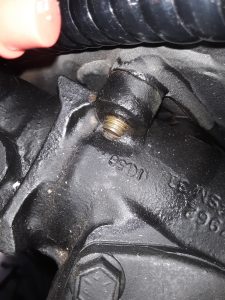
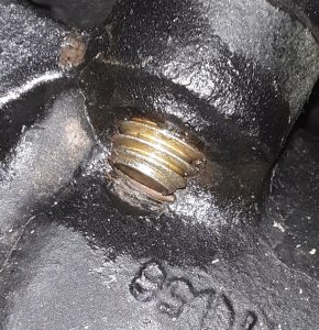
Additionally, there are five bolts installed from the outside that are tapped into the water jacket. It is important to re-apply sealant on these threads to ensure engine coolant does not leak on the threads. We used Rectorseal #5, but other products will also suffice.

UPDATE:  As we reviewed the drop-shipping invoice, the water pump is billed out as a GM 88926125. This application shows at least for civilian 1990 6.2L, and also corresponds with Airtex AW5008 indicated in a prior post.

Chinese HMMWV Parts – Are they any good?

During transit, one of the cooling fan blades on our powertrain sustained damage.  While it would likely still be serviceable under some situations, we investigated, and ultimately replaced the part with one of Chinese manufacture. 

The fan used in our unit is the same for either the 6.2 or the 6.5 NA on the v-belt application 4140-01-211-8403 [4140012118403]. We spoke with representatives of IvyWay Truck Parts  https://www.ivywaychina.com/  and acquired a manufactured-in-China fan to test and review.

The original fan is on the left, and the Ivyway fan is on the right. (note chip missing out of blade on original fan).  We went over the Ivyway fan with a caliper and could not find any difference between the two other than the Ivyway did not carry the AM General part number:

And that small gussets molded into the base of each blade. (which we determined was an improvement over the original). [Picture yet to be uploaded]

The price difference between the Ivyway and the AM General fan is a factor of about 4 times.  Additionally, we feel that the gusset molded into the blades is an improvement and should add additional strength.

We will run the Ivyway fan in our Project: M1038 to determine how well it holds up and report later if we note any issues. We do feel comfortable, however, that the quality is likely on par with the original part, especially since most plastics manfacturing is done overseas anyway. (e.g. carbon fiber bike frames, YETI coolers, etc.)

At this time, we are of the opinion this HMMWV part manufactured in China is as good, or possibly superior, to the OEM part.

Substitution: Fan Hydraulic System Bleeder

One relatively expensive and difficult to locate fitting is the bleeder valve assembly (Fig. 178, Item 3 & 4) on the line charging the fan clutch.  This assembly consists of a TEE, PIPE 4730-01-473-8047 [4730014738047], and a bleeder screw 4820-01-473-3580 [4820014733580].

The purpose of this bleeder is to ensure all air is removed from the hose leading to the fan clutch 2930-01-168-7870 [2930011687870]. Although we have since applications where the hose threads directly into the solenoid, this can be considered an upgrade to those situations. Overall,  it is generally better practice to purge air from the system at the highest point. Even if you bleed the system using the quick-coupler near the fan clutch as a bleed point, any air remaining in the hoses or fittings from the solenoid to the fan clutch may still likely travel to the highest point.

The pipe tee itself appears to be a common 1/4″ NPT Street Tee, however the perpendicular hole is instead threaded to accept a bleeder screw.

Our solution is to actually use a regular brass 1/4″ Street Tee with a specialized 1/4″ fitting incorporating a bleeder screw.

1/8″ NPT bleeder screw adapters are extremely common and easily located on eBay and Amazon. However, we wanted to avoid using a 1/8″ to 1/4″ bushing.  We were able to locate a  1/4″ NPT bleeder adapter, although it is not specifically marketed as 1/4″.  The CTA Tools 1235 Brake Bleeder Screw Repair Kit, 3/8-Inches is actually a repair fitting intended for defective brake bleeders on calipers such as Brembo and others.

As the hydraulic pressure used in the fan system is only 100 to 150 p.s.i., we feel comfortable that fittings designed to handle brake fluid pressures (800 to 2000 p.s.i (applied pressure)) should be more than sufficient.  In this application, we intend to machine the fittings so that the bleeder adapter sits as low in the fitting as possible, and will post pictures after machining.

Interchange: Water Pump Replacement

As mentioned in an earlier post, either the water pump was damaged during shipment of the powertrain, or we had damaged the water pump during the process of re-installing the body. 

Sourcing a replacement water pump is not extremely difficult, as according to the TM, the replacement part for our 6.5 NA motor is the same as for the 6.2  (PUMP,COOLING SYSTEM 6.2 LITER AND 6.5 DETUNED).  However, our book did not provide a NSN, only a p/n 23500085.  

This p/n interchanges with a number of cross interchange parts:

  • AIRTEX AW5008
  • ASC WP-598
  • ASC INDUSTRIES WP598
  • GM 12514269
  • GM 12534418

As well as many others.  (See e.g., https://www.yoyopart.com/oem/11722356/gm-23500085.html#interchange)

Depending upon where you source your water pump, and what p/n you use as basis for your search, prices seem to range from $38.00 to $395.00. With a desire to be cost effective, we traced all interchange numbers down and determined two parts were acceptable for our purpose.

  • AC Delco 252-611 ($38.37 Amazon (with coupon applied))
  • GMB 74973  ($42.95 eBay)

Of Primary Concern is the rotation of the water pump. The water pumps used in the earlier V-belt drive operate in a different rotation than the later serpentine drive pumps.  Ours is a V-belt drive meaning the water pump turns in the same direction as the crankshaft. Based on our research and purchaser comments, we purchased an AC Delco 252-611 from Amazon.

After discussing aftermarket pump reliability with Tim Grundman (owner of Big Dawg Diesel Worx, LLC), we would have felt equally comfortable with the GMB water pump, it was a combination of lower price and AC Delco being a direct GM part replacement that we chose the AC Delco pump.

Transmission Leak? It May just be an O-ring.

Occasionally leaks may occur near the modulator making you wonder if the modulator is leaking or otherwise needs rebuilt.  First check the o-ring on the fill tube where it enters the transmission case. This o-ring will harden over time and slowly start weeping oil, especially when the vehicle is parked as the fluid level will rise over the o-ring seal.

Below is a picture of a hardened, leaking o-ring.

For the 3-speed TH400 (3L80), the NSN for the o-ring is 5330-01-184-6492 [5330011846492], but can be commonly sourced at any parts house as the transmission filler tube o-ring for a TH 400 or 3L80.

Fan Shroud Bulkhead Fitting

The fan clutch is operated via a solenoid controlling power steering return fluid pressurized at approximately 100 p.s.i.  A bulkhead fitting (Fig. 178, Item 20) 4730-00-897-5497 [4730008975497] is utilized to transfer the fluid through the fan shroud.

Looking for a cost-effective substitute, we determined that this fitting is also marketed as a brass fitting called a Bulkhead Fitting, with the dimensions of 1/4″ NPT x 3/4″ long.

When we sourced this item, it came in a package of five. The price for all five was just under the price of one from a larger parts distributor, and we now have four extra on the shelves.

Interchange: Power Steering Return Hose


Determining what size hose is required to route to the cooler and the fan clutch solenoid is confusing based on the parts manual.

For example, the fitting from the return line from the cooler to the fan clutch solenoid (Fig. 178, Item 1) 4730-00-789-0951 [4730007890951] is designated as manufacturer p/n 110-03604 which is apparently an Eaton Aeroquip 90 degree brass fitting of 1/4 NPT x 5/16 hose barb.

However, the hose specified to go over the barb (Fig. 178, Item 7) is P/N 6490610019 which translates into AM General 5741209, which is assigned NSN 4720-01-186-2358 [4720011862358] and is also known as GM 6210M.

Per General Motors Corporation, the 6210M specification covers “…a 9.5 mm inside diameter hose made from textile reinforcement and synthetic rubber for use in hydraulic steering applications as a flexible connection between the power steering gear and the power steering pump or pump reservoir.”

The closest fraction to 9.5 mm is 3/8, which is exactly 9.5250 mm.  Whereas 5/16 = 7.9375 mm. We checked the dimensions of other fittings called out for use with this hose (e.g., 4730-01-481-6278 [4730014816278] ).  Its dimension is stated as “NOMINAL INSIDE DIAMETER HOSE ACCOMMODATED 0.290 INCHES 2ND END” or, slightly less than 5/16″.

We further found in the parts manual other references to P/N
6490610019, which gave an alternate AM General part number of 12338330, which is again defined as flexible hose (along with a suffix -X number) of 3/8″ diameter with applications ranging from Air Horn to CTIS (-7),  transmission (-1. -2, -5),  and power steering (-6, -9).

It seems axiomatic to use a 3/8″ hose with a 3/8″ barb fitting, not a 5/16″ barb fitting as the call out indicates.  However, throughout the parts manual it systematically calls out for 5/16″ barb fittings.

We are of the opinion that using a 5/16″ barb with a 3/8″ hose is an error. The barb itself is 1.5875 mm smaller diameter than the hose, and that means that the hose would have to be tightened considerably just to contact the shank of the barb.

We inspected the old and damaged hose removed from the 1038. There were no markings, but it appears to be a 3/8″ hose. Further, 3/8″ power steering hose is considerably more readily available commercially (and at considerably lower cost) than the 5/16″ version.

We ordered and have on hand Gates 350010 Power Steering Return Hose (which is a S.A.E. J189 Power Steering Return Hose
3/8″ x 25′ bulk package).

We can find no valid reason for the mismatch between the sizes of the fittings and the hose called out in the parts manual.

We will update or change our findings regarding the discrepancy between the parts manual call out of 5/16″ barb fittings and the use of 3/8″ hose as we complete the hydraulic plumbing of the 1038.

Interchange: Fan Quick-Disconnect


In order to make belt changing a little simpler, AM General incorporated using a quick-disconnect (Fig. 178, Item 17)  4730-01-399-0241 [4730013990241] on the hydraulic hose 4720-01-189-0853 [4720011890853]  leading to the fan clutch.

Although the quick-disconnect can be sourced as 12342947, it appears to now be marketed as an H1-62 coupler (a Parker number for the female half). This number is the female half of a 1/8″ hydraulic coupler. (Fig. 178, Item 17 actually depicts the male and female halves together) If you are lacking both parts, or if you just need to replace, search for an ISO-B hydraulic coupler in 1/8″ thread.

All couplers marked as ISO-B, regardless of manufacturer, should be interchangeable as long as they adhere to the ISO B standard (ISO 7241-B).

Above pictures are of Foster FHK Series 1/8″ H1S K1S Steel ISO B Hydraulic Quick Connect Coupler sourced from HPC in Elgin, IL.

A study in Steering Gear Bolts

As discussed in an earlier article, there are two 7/16-14 x 5.25 bolts 5305-01-213-4149  [5305012134149]  and one 7/16-14 x 4.00 5306-01-254-6356 [5306012546356] required to mount the steering gear to the frame. The 5.25″ length can be sourced as GM 9430761, however the 4″ bolt as MS35764-861 is not easily sourced, but 4″ long bolts are a standard length, unlike the 5 1/4″ length.

This article is about whether the length is that critical.  We do not believe so. (but read “word of caution” at end of article) For restorative purposes you may want the length to be as close as possible, or if not, to otherwise serve as a useful upgrade.

The picture below shows the clearance against the steering box when using the 4″ long bolt:

Note that the bolt extends through nearly 1/4″, and would likely have extended slightly further had we used a standard Grade 8 SAE washer instead of the “extra heavy” ones that we did. Further note that the end of the bolt can actually butt against the housing, the threads do not go above or across the top of the housing. Ensure that the end of the bolt does not butt up against the housing, which will result in a false reading with a torque wrench.

Note there isn’t a tremendous amount of clearance between the end of the bolt and the housing itself.  You can see that it was threaded into the housing so the bolt didn’t bottom out.

Ensure that whatever bolt/washer combination you use in the 4″ location that the bolt does not deadhead against the housing. (this would likely result in the upper boss of the steering gear not being drawn tight into the frame as well as causing an erroneous reading with a torque wrench.)

What about substituting longer or shorter bolts?

For the 4″ length bolt, the next shorter standard length would be 3 1/2″, and although that would at least partially engage most of the threads in the boss, we would advise against it except under emergency circumstances since this boss is the only one of the top two that even gets a bolt.

Our opinion changes slightly on the two lower 5 1/4″ length bolts.

In the picture above, you can see how far the 5 1/4″ lower bolts extend past the bosses in the steering gear. There is no doubt that a 5 1/2″ bolt might work (assuming the threaded section of the bolt is long enough and doesn’t bottom out in the boss).

Pictured above are (top bolt), the sole 5 1/4″ bolt remaining in the M1038. The middle bolt is the GM 9430761 discussed above, and the bottom bolt is one supplied by one of the “big 3″ suppliers. The bottom bolt is in fact, a 5 1/2″ length bolt. Because we had concerns that the threads would not be long enough (and bottom out in the boss) we chose to not use the 5 1/2″ bolt and acquired the proper length of 5 1/4.” It is likely that people may have erroneously replaced this bolt with the incorrect length which could potentially lead to a dangerous situation.

In our opinion, the most rearward of the lower bolts could be a 5″ long bolt without any adverse issues. As we installed it, it is nearly 1/2″ past the boss. The frontward one could also likely get by with a 5″ length bolt and still thread completely into the boss.

A word of caution, however, is that the steering is one area you don’t really want to take risks in. You limit your liability and ensure vehicle safety by using the correct fasteners, or at least the correct length of fasteners called out by the manufacturer.

Steering Gear Mounting

As luck would have it, the steering gear on our project M1038 had only one bolt holding it to the frame. Fig. 171 (of TM 9-2320-280-24P-1), shows two different bolts attaching the steering gear to the frame.

The sole remaining bolt was 5 1/4″ long. According to the call out in the Parts Manual, this corresponded with Item 5,  5305-01-213-4149 [5305012134149].  Unfortunately, however, it was virtually impossible to locate a 5 1/4″ Grade 8 bolt, as the common sizes are 5″ or 5 1/2.”

Although some of the “big 3” indicate that a bolt kit is available for the steering gear fasteners as 5745684, when we ordered it, we were told it was on backorder from AM General, and at least one seller indicated that the kit was simply “discontinued.”

We cancelled the backorder and tried sourcing again. We were able to find a seller on eBay selling “GM Hex Head Cap Screw Bolt 9430761  7/16″-14 x 5.25 Grade-8 UNC.”

As it turns out, 9430761 is the manufacturer’s part number for this bolt, and being as it is a GM steering box, it makes sense that GM would be the supplier. Although we had to purchase five bolts, when we technically only needed one (there was one remaining), we have extra bolts in the event they are needed in the future by us or others.

The callout for the remaining bolt (Item 4) is 5306-01-254-6356  [5306012546356] which is described as: “BOLT, SELF-LOCKING 7/16-14 X 4.00″  Although 4″ is a common length, we were not able to source this specific bolt (MS35764-861) and substituted it with a standard 7/16″-14 x 4” Grade 8 bolt.

It is not uncommon for steering boxes to loosen up over a period of time. We originally opted to use Nord-Lock lock washers in place of the split lock washer. However, in the interest of attempting to keep the project as original in appearance, we instead used Grade 8 split lock washers and heavy 7/16″ Grade 8 SAE washers instead. All three bolts were installed with blue loctite and torqued to 60 ft-lbs.

Torque specifications and use of blue Loctite are as recommended by flashoffroad.com in their chart located at:  http://www.flashoffroad.com/Maintenance/Specs/torqueSpecs/HMMWVTorque.htm  (opens in new window)